![brake force on each wheel [15].A block diagram model of a brake control system is shown in Figure E2.9, where F(s) and FR(S)](http://img.homeworklib.com/images/8458f02b-9619-4581-b680-1839976c1162.png?x-oss-process=image/resize,w_560)
Homework Answers


Add Answer to:
Solve 2.8 Please brake force on each wheel [15].A block diagram model of a brake control system is shown in Figure E...
automobile uses electronic feedback to control au brake force on each wheel [15].A block of a brake control system...
 automobile uses electronic feedback to control au brake force on each wheel [15].A block of a brake control system is shown where F(s) and Fa(s) front and rear wheels, respectively desired automobile response on an F()R(s) level of light. A control engineer, N. Minorsky, designed an inno- vative ship steering system in the 1930s for the U.S Navy. The system is represented by the block diagram shown in Figure E2.8, where Y(s) is the ship's course, R(s) is the desired...
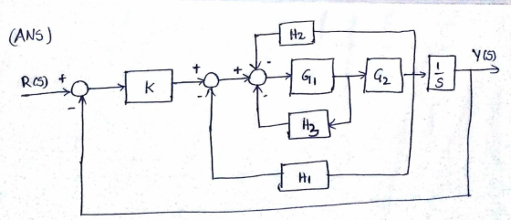
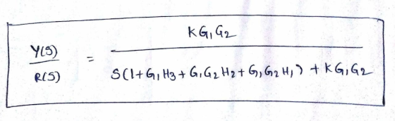
For the block diagram of a feedback control system that is shown in Figure Q1 below,...
 For the block diagram of a feedback control system that is shown in Figure Q1 below, find the transfer function Ts) Y(s) /R(s) for the system. 2 R(s) Y(s) :? 2 2 Figure Q1
1. (30 points) The block diagram of a machine-tool control system is shown in Figure 1. (a) (10 p...
 1. (30 points) The block diagram of a machine-tool control system is shown in Figure 1. (a) (10 points) Determine the transfer function H(s) = Y(s)/R(s) (b) (10 points) Determine the sensitivity S (c) (10 points) For 1
3-21. The block diagram of a control system is shown in Fig. 3P-21. (a) Draw an...
 3-21. The block diagram of a control system is shown in Fig. 3P-21. (a) Draw an equivalent SFG for the system. (b) Find the following transfer functions by applying the gain formula of the SFG directly to the block diagram. Y(s) Y(s) E(s) E(s) R(s)[N=0 N(s)R=0 R(s) N= N(s) R-0 (c) Compare the answers by applying the gain formula to the equivalent SFG. N() G (s) E(s) YS G () G3(s) H () Figure 3P-21
8-24. The block diagram of a de-motor control system is shown in Fig. 8P-24. Determine the range ...
 8-24. The block diagram of a de-motor control system is shown in Fig. 8P-24. Determine the range of K for stability using the Nyquist criterion when K, has the following values (a) K0 (b) K 0.01 R(s) E(s) Y(s) 10 +0.1 0.01s Figure 8P-24
8-24. The block diagram of a de-motor control system is shown in Fig. 8P-24. Determine the range of K for stability using the Nyquist criterion when K, has the following values (a) K0 (b) K 0.01...
8-24. The block diagram of a de-motor control system is shown in Fig. 8P-24. Determine the range of K for stability using the Nyquist criterion when K, has the following values (a) K0 (b) K 0.01 R(s) E(s) Y(s) 10 +0.1 0.01s Figure 8P-24
8-24. The block diagram of a de-motor control system is shown in Fig. 8P-24. Determine the range of K for stability using the Nyquist criterion when K, has the following values (a) K0 (b) K 0.01...
In the block diagram of the feedback control system shown in figure below, Gp(s) is the...
 In the block diagram of the feedback control system shown in figure below, Gp(s) is the transfer function of a process, R(s) is reference input, and A(s) and H(s) represent controllers. N(S) R(s) Gp(s) Process A(s) H(s) = _100_ , and H(s)-1 / GAS). Let Gs)-A(S)5.and Find the steady state value of the response C(t), when N(t) = R(t) = unit-step function. Is this also the maximum value attained by the response? Justify your answers. (s2+2s+4)
QI. The block diagram representing a mechanical system is shown in Figure 1(a). The desired set...
 QI. The block diagram representing a mechanical system is shown in Figure 1(a). The desired set point to controllers is r(t) = 50. The system vibrates as shown in Figure 1(b). (1) Find the transfer function of C(s) /R(s) by reducing the block diagram (in) Determine the value of a and b (ii) Find the steady state error of the system Figure 1(a) Time (seconds) Figure 1(b) ANSWER Transfer function, 0.12b +0.12 0.12as +012bs + 0.125 + 1 () Mp....
4 (a) Based on the block diagram for a control system (Figure Q4(a) below) determine the...
 4 (a) Based on the block diagram for a control system (Figure Q4(a) below) determine the transfer function between the error and the set point, E(s)/R(s) (8 marks) R(s)+ c(p) m(s) Figure Q4(a) Figure Q4(b) below shows two different control strategies for a continuous stirred tank reactor (CSTR). The reaction A → B is exothermic and the heat generated is removed by the coolant flowing through the jacket. It is assumed the flowrate of the reactor feed is fixed. Two...
b) Following figure shows a block diagram of a control system. Obtain the characteristics equation of...
 b) Following figure shows a block diagram of a control system. Obtain the characteristics equation of the system. [5 marks] Determine the limiting value of K for stability using Routh's criterion. [10 marks] R(S) 20 C(s) 4K S +1 2s+1 0.2 Fig. Q3
control system System Description: The figure 1 and 2 below show, respectively, components and block diagram...
 control system
System Description: The figure 1 and 2 below show, respectively, components and block diagram of a motor and the measurements of velocity (via the tacho unit) and position (via the potentiometer). n represents the gearbox ratio between the rotating shaft and the output shaft. The left-hand side of the diagram represents the controller. A reference set point for the rotating shaft is entered in degrees and this is equivalent voltage. The error is calculated by subtracting the measured...
control system
System Description: The figure 1 and 2 below show, respectively, components and block diagram of a motor and the measurements of velocity (via the tacho unit) and position (via the potentiometer). n represents the gearbox ratio between the rotating shaft and the output shaft. The left-hand side of the diagram represents the controller. A reference set point for the rotating shaft is entered in degrees and this is equivalent voltage. The error is calculated by subtracting the measured...
 automobile uses electronic feedback to control au brake force on each wheel [15].A block of a brake control system is shown where F(s) and Fa(s) front and rear wheels, respectively desired automobile response on an F()R(s) level of light. A control engineer, N. Minorsky, designed an inno- vative ship steering system in the 1930s for the U.S Navy. The system is represented by the block diagram shown in Figure E2.8, where Y(s) is the ship's course, R(s) is the desired...
 For the block diagram of a feedback control system that is shown in Figure Q1 below, find the transfer function Ts) Y(s) /R(s) for the system. 2 R(s) Y(s) :? 2 2 Figure Q1
 1. (30 points) The block diagram of a machine-tool control system is shown in Figure 1. (a) (10 points) Determine the transfer function H(s) = Y(s)/R(s) (b) (10 points) Determine the sensitivity S (c) (10 points) For 1
 3-21. The block diagram of a control system is shown in Fig. 3P-21. (a) Draw an equivalent SFG for the system. (b) Find the following transfer functions by applying the gain formula of the SFG directly to the block diagram. Y(s) Y(s) E(s) E(s) R(s)[N=0 N(s)R=0 R(s) N= N(s) R-0 (c) Compare the answers by applying the gain formula to the equivalent SFG. N() G (s) E(s) YS G () G3(s) H () Figure 3P-21
 8-24. The block diagram of a de-motor control system is shown in Fig. 8P-24. Determine the range of K for stability using the Nyquist criterion when K, has the following values (a) K0 (b) K 0.01 R(s) E(s) Y(s) 10 +0.1 0.01s Figure 8P-24
8-24. The block diagram of a de-motor control system is shown in Fig. 8P-24. Determine the range of K for stability using the Nyquist criterion when K, has the following values (a) K0 (b) K 0.01...
8-24. The block diagram of a de-motor control system is shown in Fig. 8P-24. Determine the range of K for stability using the Nyquist criterion when K, has the following values (a) K0 (b) K 0.01 R(s) E(s) Y(s) 10 +0.1 0.01s Figure 8P-24
8-24. The block diagram of a de-motor control system is shown in Fig. 8P-24. Determine the range of K for stability using the Nyquist criterion when K, has the following values (a) K0 (b) K 0.01...
 In the block diagram of the feedback control system shown in figure below, Gp(s) is the transfer function of a process, R(s) is reference input, and A(s) and H(s) represent controllers. N(S) R(s) Gp(s) Process A(s) H(s) = _100_ , and H(s)-1 / GAS). Let Gs)-A(S)5.and Find the steady state value of the response C(t), when N(t) = R(t) = unit-step function. Is this also the maximum value attained by the response? Justify your answers. (s2+2s+4)
 QI. The block diagram representing a mechanical system is shown in Figure 1(a). The desired set point to controllers is r(t) = 50. The system vibrates as shown in Figure 1(b). (1) Find the transfer function of C(s) /R(s) by reducing the block diagram (in) Determine the value of a and b (ii) Find the steady state error of the system Figure 1(a) Time (seconds) Figure 1(b) ANSWER Transfer function, 0.12b +0.12 0.12as +012bs + 0.125 + 1 () Mp....
 4 (a) Based on the block diagram for a control system (Figure Q4(a) below) determine the transfer function between the error and the set point, E(s)/R(s) (8 marks) R(s)+ c(p) m(s) Figure Q4(a) Figure Q4(b) below shows two different control strategies for a continuous stirred tank reactor (CSTR). The reaction A → B is exothermic and the heat generated is removed by the coolant flowing through the jacket. It is assumed the flowrate of the reactor feed is fixed. Two...
 b) Following figure shows a block diagram of a control system. Obtain the characteristics equation of the system. [5 marks] Determine the limiting value of K for stability using Routh's criterion. [10 marks] R(S) 20 C(s) 4K S +1 2s+1 0.2 Fig. Q3
 control system
System Description: The figure 1 and 2 below show, respectively, components and block diagram of a motor and the measurements of velocity (via the tacho unit) and position (via the potentiometer). n represents the gearbox ratio between the rotating shaft and the output shaft. The left-hand side of the diagram represents the controller. A reference set point for the rotating shaft is entered in degrees and this is equivalent voltage. The error is calculated by subtracting the measured...
control system
System Description: The figure 1 and 2 below show, respectively, components and block diagram of a motor and the measurements of velocity (via the tacho unit) and position (via the potentiometer). n represents the gearbox ratio between the rotating shaft and the output shaft. The left-hand side of the diagram represents the controller. A reference set point for the rotating shaft is entered in degrees and this is equivalent voltage. The error is calculated by subtracting the measured...
Most questions answered within 3 hours.
-
Do not neglect the old for the new. The existing business must
not lose priority simply...
asked 2 hours ago -
Kylie is a single mom with two dependent children,
Tanner, age 7 and Olivia, age 11....
asked 3 hours ago -
Phosphorous + bromine = phosphorous tribromide. If 35.0 g of
bromine are reacted and 27.9 grams...
asked 5 hours ago -
Derive the long wavelength limit of the Planck energy density
distribution
asked 5 hours ago -
Calculate the pH of each of the following solutions.
0.50 M HBr
3.1×10⁻⁴ M KOH
4.2×10⁻⁵...
asked 8 hours ago -
For the year ended December 31, Depot Max’s cost of merchandise
sold was $85,600. Inventory at the...
asked 8 hours ago -
Week 10 - Professional Memo Assignment
Professional Memo Assignment
Your mission for this week, should you...
asked 8 hours ago -
Write a Python program that stores the data for each
player on the team, and it...
asked 9 hours ago -
In
the last 3 months, mike never knows when he is going to get his
allowance...
asked 9 hours ago -
Is Ca(OH)2 a Bronsted base, Lewis base, or both? Why?
asked 9 hours ago -
1A- Why don’t voters complain about U.S. tariffs on imported
sugar?
Because sugar is only a...
asked 9 hours ago -
Cash Payback Period
Primera Banco is evaluating two capital investment proposals for
a drive-up ATM kiosk,...
asked 9 hours ago