
Please I need help to solve these problems
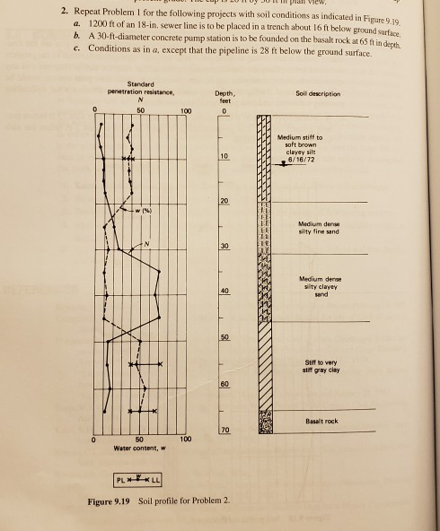
Repeat Problem I for the following projects with soil conditions as indicated in Figure 9 a. b. c. 2. gure 9.19 1200 ft of an 18-in. sewer line is to be placed in a trench about 16 ft below A 30-ft-diameter concrete pump station is to be founded on the basalt rock at 65 ft in depth Conditions as in a, except that the pipeline is 28 ft below the ground surface. Standard penwtration resistance, Depth Soil description 50 100 Medium stiff to soft brown clayey silt 10 6/16172 Medium dee ilty fine sand 30 1t Medium dense slty clayey and 40 Stff to very stif gray clay 60 Basalit rock 70 100 50 Water content, w Figure 9.19 Soil profile for Problem 2.
Homework Answers
Answer:
1.a)for the given construction conditions for circular reservoir and the soil conditions the dewatering methods may be followed are well point system and ejector system.
for the given condition of reservoir the required dewateing depth is about 9 ft.total depth of reservoir below the ground is 25 ft.the min depth of water level below the cap is 2 ft.the water level from the groung level is at arround 18 ft.then the rrrequirred depth of dewatering is 25+2-18 = 9ft.
for this depth of dewatering and the type of given sand and siltysoil the method of dewatering adopted is well point system and ejector systems.
but in this case we are adopting wellpoint system.the method includes porviding perforated pipes of metal or plastic of 5.0to12.0 cm dia whose bottom end is also perforated and connected to bottom of the water level which are rised above (rised pipes) and these are connected to the header pipe.the water from the bottom levelis rised throuh this header pipe and discharged by connecting these header pipe to the pumps.these pumps will discharge thewater from the pits and lowers the water level upto 30 ft in this method.
the main problems which involves in this method includes the stability of the slope and the blocking of the perforatedd pipes due to the debris.and the air is entered into the pipes through the joints of the pipe and it will reduce ethe pump effeciency.these entry of debris can be over come by providing screens at the bottom.and the entry of air can be limted by providing tight seal joints.
2)The strategies for dewatering utilized for the different activities are as per the following:
a) Wellpoint strategy for dewatering can be utilized for the case. This is on account of sewer line should be put at a profundity of 16ft subterranean level henceforth wellpoint technique would be adequate to make legitimate drawdown as this strategy is limited to make drawdown around 5 to 6 meters beneath the wellpoint pump level. Since the dirt layer experienced has low penetrability henceforth wellpoint strategy will be favored. Since the geologic conditions experienced likewise allow close separating of gadgets.
b) Deep well strategy for dewatering can be utilized as a part of this case. This is on account of the pump station is to be established on basalt shake which is 65ft profound and for the profound well technique the profundity of the wells could reach upto 30m.
c) Open sump directing technique for dewatering can be utilized as a part of this case. This is on account of the pipeline must be laid at 28ft subterranean surface in sandy soils.
The troubles that might be experienced and the means that could be taken to counter with the challenges are:
1) Creating profound well upto the level of basaltic shake might be troublesome.
The boring piece ought to be tipped with hard cutting material (Tungsten Carbide or mechanical precious stone) connected to the penetrate bar through a sledge system in the middle. Compacted air is utilized both for pivoting the bore bar and in addition creating a consistent pounding activity on the joined bore.
2) Installation of wellpoint framework could be minimal costly.
Supporting conditions should be enhanced to avert disappointment of the dewatering framework.
3) For profound well frameworks the measure of intensity required to work the pump couldn't be legitimately accessible in specific zones where access to powergrid isn't appropriate.
The alernative backup choice for power ought to be masterminded heretofore for the areas of profound well dewatering.
Add Answer to:
PROBLEMS 1. Figure 9.18 is representative of soil conditions at a construction site. If you are t...
Need help on this problem 0 Figure 5.17 Problem 1. Soil profile for Medium sand γ...
 Need help on this problem
0 Figure 5.17 Problem 1. Soil profile for Medium sand γ = 1 1 0 pcf 10 Medium sand γ 124 pct O. 32 Stiff clay γ 100 pcf 50 Basalt rock uios i depin A 25-ft-diameter concrete caisson is to be sunk to the rock surface shown in Figure 5.17 at a depth of 50 ft. Describe, using sketches where appropriate, how you would do it, and what problems you might encounter. 4. 5....
Need help on this problem
0 Figure 5.17 Problem 1. Soil profile for Medium sand γ = 1 1 0 pcf 10 Medium sand γ 124 pct O. 32 Stiff clay γ 100 pcf 50 Basalt rock uios i depin A 25-ft-diameter concrete caisson is to be sunk to the rock surface shown in Figure 5.17 at a depth of 50 ft. Describe, using sketches where appropriate, how you would do it, and what problems you might encounter. 4. 5....
2. Grain size distribution for three different soils is given on Figure 1. For SOIL 3,...
 2. Grain size distribution for three different soils is given on Figure 1. For SOIL 3, answer the following questions: (5 points) a. What is the perentage of gravel, sand, and fines? b. Classify the soil according to the ASTM/USCS (i.e, give both the Group Symbol and Group Name) (1) U.S. Standard sieve size in 3 in 100 No. 4 No. 10 No. 40 No. 200 90 80 70 60 50 40 30 20 10 0 100 10 1.0 0.1...
Please see picture below for question #1, parts a-d. Do you agree with my answers ?...
 Please see picture below for question #1, parts a-d. Do you
agree with my answers ?
a. 25 borings seems like enough for a 100' x 100' building,
that's 4 every 25ft.
b. Borings are only 20 feet, I feel like this should be deeper
for a 3-story building on poor soil. I would bore to 40ft.
c. If the number or depth of borings seem inadequate, as does
the depth of the borings, I'd have them done to a...
Please see picture below for question #1, parts a-d. Do you
agree with my answers ?
a. 25 borings seems like enough for a 100' x 100' building,
that's 4 every 25ft.
b. Borings are only 20 feet, I feel like this should be deeper
for a 3-story building on poor soil. I would bore to 40ft.
c. If the number or depth of borings seem inadequate, as does
the depth of the borings, I'd have them done to a...
Homework #10 A soil exploration result of a site is shown in the following figure. A...
 Homework #10 A soil exploration result of a site is shown in the following figure. A building is to be constructed at that site. First, it has been proposed to raise the elevation of the ground by filling the site with 10 ft thick compacted soil at an area of 25 ft x 25 ft. The unit weight of the compacted moist soil was 120 pcf. The foundation of proposed building was constructed at the center of the compaction area...
[Problems 1-4] The soil profile at a site for a proposed office building consists of a...
 [Problems 1-4] The soil profile at a site for a proposed office building consists of a layer of fine sand 10.4 m thick above a layer of soft, normally consolidated clay 2 m thick. Below the soft clay is a deposit of coarse sand. The groundwater table was observed at 3 m below ground level. The void ratio of the sand is 0.76, and the water content of the clay is 43%. The building will impose a vertical stress increase...
Q8 An oil tank, 20 m in diameter, is to be built on a site where the soil profile consists of 4 m of dense gravel overl...
 Q8 An oil tank, 20 m in diameter, is to be built on a site where the soil profile consists of 4 m of dense gravel overlying 3 m of clay overlying rigid impermeable rock, and the water table is 1 m below the soil surface. If the tank applies a uniform pressure of 100 kPa to the surface of the soil calculate the differential settlement between the centre and perimeter of the tank after 1 year and after many...
Question 5 (Effective Stress & Consolidation) Figure 05 shows the soil profile of a construction site....
 Question 5 (Effective Stress & Consolidation) Figure 05 shows the soil profile of a construction site. The water table is at the ground surface. Saturated unit weight of the sand is 18.8kN/m' and that of the clay is 19.6kN/m. Assume permeability of the clay is very low and unit weight of water is 10kN/m'. Water Table Sand 5m Clay 6m Figure 05 a) Determine the vertical total stress, pore water pressure, and vertical effective stress at the mid-height of the...
Referring to below borehole log. Referring specifically to information provided on the borehole log- Would this...
 Referring to below borehole log. Referring specifically to
information provided on the borehole log- Would this borehole lend
itself to standard methods of construction for a large wastewater
treatment plant? What geotechnical aspects might you need to
consider during design and construction phases?
[20
Figure 2 Borehole log Holst Soil Engineering Limited Borehole No BOREHOLE LOG Location. Davyhulse Sewage Worke. ST 79 NE - 287 Sheet 1 of 2 5253 964.95 Ground Level 20.23 A.0.D. Contract No . 3256 Client...
Referring to below borehole log. Referring specifically to
information provided on the borehole log- Would this borehole lend
itself to standard methods of construction for a large wastewater
treatment plant? What geotechnical aspects might you need to
consider during design and construction phases?
[20
Figure 2 Borehole log Holst Soil Engineering Limited Borehole No BOREHOLE LOG Location. Davyhulse Sewage Worke. ST 79 NE - 287 Sheet 1 of 2 5253 964.95 Ground Level 20.23 A.0.D. Contract No . 3256 Client...
1. A 12-story residential apartment is about to be built. The site investigate has been completed and the soil strata information is provided. The area of the footprint of the building is 100...
 1. A 12-story residential apartment is about to be built. The site investigate has been completed and the soil strata information is provided. The area of the footprint of the building is 100 x200 ft2 and the height of the building is 180 ft. The estimated vertical dead load of each story is 1000 kips and vertical live load is 15 psf. Based on the FEMA database, the building may be subjected to category S hurricane. a. Please design drilled...
Deadline: 4pm, Thursday, Oct 10. Hand in the submission electronically in DOC, PDF, or JPEG format)...
 Deadline: 4pm, Thursday, Oct 10. Hand in the submission electronically in DOC, PDF, or JPEG format) through MyUni Assignment online portal. Late submissions penalised 5% per day. Plagiarism will be penalised severely. 1. (10 marks): This tutorial continues Tutorial No. 4. The soil profile for proposed roadway construction is represented in Figure 1. A soil sample was recovered at A, and was tested in an oedometer device. The test results are provided in Table 1. The void ratio of the...
 Need help on this problem
0 Figure 5.17 Problem 1. Soil profile for Medium sand γ = 1 1 0 pcf 10 Medium sand γ 124 pct O. 32 Stiff clay γ 100 pcf 50 Basalt rock uios i depin A 25-ft-diameter concrete caisson is to be sunk to the rock surface shown in Figure 5.17 at a depth of 50 ft. Describe, using sketches where appropriate, how you would do it, and what problems you might encounter. 4. 5....
Need help on this problem
0 Figure 5.17 Problem 1. Soil profile for Medium sand γ = 1 1 0 pcf 10 Medium sand γ 124 pct O. 32 Stiff clay γ 100 pcf 50 Basalt rock uios i depin A 25-ft-diameter concrete caisson is to be sunk to the rock surface shown in Figure 5.17 at a depth of 50 ft. Describe, using sketches where appropriate, how you would do it, and what problems you might encounter. 4. 5....
 2. Grain size distribution for three different soils is given on Figure 1. For SOIL 3, answer the following questions: (5 points) a. What is the perentage of gravel, sand, and fines? b. Classify the soil according to the ASTM/USCS (i.e, give both the Group Symbol and Group Name) (1) U.S. Standard sieve size in 3 in 100 No. 4 No. 10 No. 40 No. 200 90 80 70 60 50 40 30 20 10 0 100 10 1.0 0.1...
 Please see picture below for question #1, parts a-d. Do you
agree with my answers ?
a. 25 borings seems like enough for a 100' x 100' building,
that's 4 every 25ft.
b. Borings are only 20 feet, I feel like this should be deeper
for a 3-story building on poor soil. I would bore to 40ft.
c. If the number or depth of borings seem inadequate, as does
the depth of the borings, I'd have them done to a...
Please see picture below for question #1, parts a-d. Do you
agree with my answers ?
a. 25 borings seems like enough for a 100' x 100' building,
that's 4 every 25ft.
b. Borings are only 20 feet, I feel like this should be deeper
for a 3-story building on poor soil. I would bore to 40ft.
c. If the number or depth of borings seem inadequate, as does
the depth of the borings, I'd have them done to a...
 Homework #10 A soil exploration result of a site is shown in the following figure. A building is to be constructed at that site. First, it has been proposed to raise the elevation of the ground by filling the site with 10 ft thick compacted soil at an area of 25 ft x 25 ft. The unit weight of the compacted moist soil was 120 pcf. The foundation of proposed building was constructed at the center of the compaction area...
 [Problems 1-4] The soil profile at a site for a proposed office building consists of a layer of fine sand 10.4 m thick above a layer of soft, normally consolidated clay 2 m thick. Below the soft clay is a deposit of coarse sand. The groundwater table was observed at 3 m below ground level. The void ratio of the sand is 0.76, and the water content of the clay is 43%. The building will impose a vertical stress increase...
 Q8 An oil tank, 20 m in diameter, is to be built on a site where the soil profile consists of 4 m of dense gravel overlying 3 m of clay overlying rigid impermeable rock, and the water table is 1 m below the soil surface. If the tank applies a uniform pressure of 100 kPa to the surface of the soil calculate the differential settlement between the centre and perimeter of the tank after 1 year and after many...
 Question 5 (Effective Stress & Consolidation) Figure 05 shows the soil profile of a construction site. The water table is at the ground surface. Saturated unit weight of the sand is 18.8kN/m' and that of the clay is 19.6kN/m. Assume permeability of the clay is very low and unit weight of water is 10kN/m'. Water Table Sand 5m Clay 6m Figure 05 a) Determine the vertical total stress, pore water pressure, and vertical effective stress at the mid-height of the...
 Referring to below borehole log. Referring specifically to
information provided on the borehole log- Would this borehole lend
itself to standard methods of construction for a large wastewater
treatment plant? What geotechnical aspects might you need to
consider during design and construction phases?
[20
Figure 2 Borehole log Holst Soil Engineering Limited Borehole No BOREHOLE LOG Location. Davyhulse Sewage Worke. ST 79 NE - 287 Sheet 1 of 2 5253 964.95 Ground Level 20.23 A.0.D. Contract No . 3256 Client...
Referring to below borehole log. Referring specifically to
information provided on the borehole log- Would this borehole lend
itself to standard methods of construction for a large wastewater
treatment plant? What geotechnical aspects might you need to
consider during design and construction phases?
[20
Figure 2 Borehole log Holst Soil Engineering Limited Borehole No BOREHOLE LOG Location. Davyhulse Sewage Worke. ST 79 NE - 287 Sheet 1 of 2 5253 964.95 Ground Level 20.23 A.0.D. Contract No . 3256 Client...
 1. A 12-story residential apartment is about to be built. The site investigate has been completed and the soil strata information is provided. The area of the footprint of the building is 100 x200 ft2 and the height of the building is 180 ft. The estimated vertical dead load of each story is 1000 kips and vertical live load is 15 psf. Based on the FEMA database, the building may be subjected to category S hurricane. a. Please design drilled...
 Deadline: 4pm, Thursday, Oct 10. Hand in the submission electronically in DOC, PDF, or JPEG format) through MyUni Assignment online portal. Late submissions penalised 5% per day. Plagiarism will be penalised severely. 1. (10 marks): This tutorial continues Tutorial No. 4. The soil profile for proposed roadway construction is represented in Figure 1. A soil sample was recovered at A, and was tested in an oedometer device. The test results are provided in Table 1. The void ratio of the...
Most questions answered within 3 hours.
-
An entomologist discovers a dung beetle rolling a ball of dung
along the ground, and decides...
asked 21 minutes ago -
Humans have used horses for transportation for millions of
years. Therefore, they will use horses for...
asked 2 hours ago -
The following are the Jensen Corporation's unit costs of making
and selling an item at a...
asked 2 hours ago -
Does direct Medicare reimbursement of Advanced practice nurses
increase access to their services?
asked 3 hours ago -
List and explain why a company would choose to use a
published
compensation survey vs. creating...
asked 3 hours ago -
A discrete random variable X can take values from 1 to 10. Find
the variance of...
asked 4 hours ago -
The primary financial goal of a corporation is to maximize:
shareholders wealth.
earnings per share.
stock...
asked 4 hours ago -
determine whether the vectors u=(1,2,3,), v=(-2,1,0) and
w=(1,0,1) are linearly dependent or independent.
asked 4 hours ago -
python
Define a function called print_values which takes a dictionary
object as a parameter. The function...
asked 5 hours ago -
In Chapter 1 you created a program named Triangle in
which you displayed a seven-line triangle...
asked 5 hours ago -
Research question: What are the differences between separately
stated and non separately stated transactions in an...
asked 5 hours ago -
By using Arduino write a code that connects two LEDs to two
push-buttons. Each button controls...
asked 6 hours ago