
Homework Answers


Add Answer to:
We may design a DC power supply by cascading a fullwave rectifier and an RC circuit as depicted b...
We may design a dc power supply by cascading a full-wave rectifier and an RC circuit....
 We may design a dc power supply by cascading a full-wave rectifier and an RC circuit. The full wave rectifier output x(t) = |cos(120t)I is the input to the RC circuit whose frequency response is 4. a) Find the Fourier transform for the input signal x(t) b) Find the Fourier transform for the output signal y(t) c) Find the range for the RC such that magnitude of the first harmonic of the ripple in y(t) is less than 1% of...
1. Power supply (ac to dc) design. [10 pts.] Design a full-wave bridge rectifier circuit to deliv...
 1. Power supply (ac to dc) design. [10 pts.] Design a full-wave bridge rectifier circuit to deliver 10 volts dc with less than 0.1 volt (peak to peak) ripple into a load drawing up to 10 mA. (a) Choose the appropriate ac input voltage from the transformer secondary assuming the usual voltage drops for silicon diodes. (b) Determine the correct capacitor value to ensure the specified ripple in your calculation (c) What fuse value should you select for the primary...
It is required to use a FULL-wave rectifier to design a dc power supply that provides...
It is required to use a FULL-wave rectifier to design a dc power supply that provides an average dc output voltage of 15 V. A maximum ripple voltage of ±1 V is allowed on the output voltage. The output voltage will feed a load resistance of 250 Ω. Assume a sinusoidal input voltage with the frequency of 60 Hz. Do not include a Zener diode in your design. (Assume V_D0)* = 0.7 V). a) Draw the circuit diagram. b) Calculate...
2. Suppose we want to design a de power supply by filtering the output, Vree(t), of...
 2. Suppose we want to design a de power supply by filtering the output, Vree(t), of a full-wave rectifier through the following low-pass filter Choke-Input Filter Pulsating DC From Rectifier Filtered DC Output To Load Assume that the trigonometric Fourier series expansion of Vree t) is given by: Vree(t)-Vpsin(2T50t) n(1-4n2) a) From known properties of linear systems, write down an expression for the steady state output of the filter b) What are the amplitudes of the de component and the...
Q 4 (after Problem 3.62) 6 marks One technique for building a DC power supply is...
 Q 4 (after Problem 3.62) 6 marks One technique for building a DC power supply is to take an AC signal and full- wave rectify it. That is, we put the AC signal x(t) through a system that produces y(t) = x(0)| as its output. (a) Sketch the input and output waveforms if x(t) = cos(t. What are the fundamental periods of the input and output? (b) determine the Fourier series coefficients for the output y(t) = X(t). (c) What...
3. (35 pts) Consider a standard RLC circuit with a resistor R, inductor L and capacitor C all in ...
 3. (35 pts) Consider a standard RLC circuit with a resistor R, inductor L and capacitor C all in series driven by a voltage source v(t). The voltage source gives pulses of 5 volts that last 1 msec every 10 msec, i.e. a square wave with period 10. We are interested in the output y(t) which is the current flowing through the circuit at time t. (a) Find a general expression for the frequency response H(jw) of this system (b)...
In this part of the term paper, design a single-phase switch-mode DC power supply with a forward ...
 In this part of the term paper, design a single-phase switch-mode DC power supply with a forward converter. Provide answers to the questions below Please combine the single-phase full-wave rectifier from part two of your term paper with a forward converter to produce a switch-mode DC power supply, as shown below. The output of the bridge rectifier serves as input to the forward converter L1 Np: N BH621BH62 D, V1 Load C1 100p 45 Vrms D3 BH62 18H62 D4 Control...
solve 2.40 a,b,c, e using Fourier series. 2.40 part a,b,c,e 2.40 Consider the continuous-time signals depicted in Fig. P2.40. Evaluate the following convolution integrals: (a) m(t) x(t) y(t) (...
 solve 2.40 a,b,c, e using Fourier series.
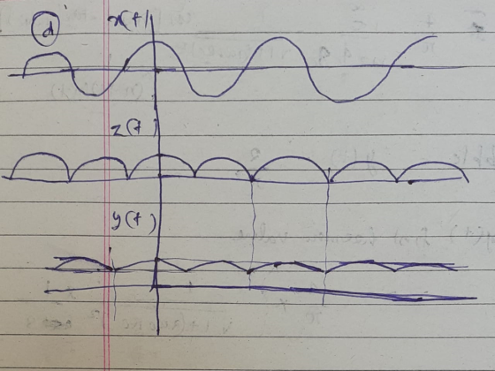
2.40 part a,b,c,e 2.40 Consider the continuous-time signals depicted in Fig. P2.40. Evaluate the following convolution integrals: (a) m(t) x(t) y(t) (b) m(t)x(t)z(t) (c) m(t) x(t) ft) (d) m(t) x(t) a(t) (e) m(t)y(t) z(t) (f) m(t) -y(t) w(t) (g) m(t) y(t)g(t) (h) m(t)y(t) c(t) (i) m(t) z(t) f(t) (j) m(t) z(t) g(t) (k) m(t) z(t)b(t) (1) m(t) w(t) g(t) (m) m(t) w(t) a(t) (n) m(t) f(t) g(t (o) m(t) fo) . do) (p)...
solve 2.40 a,b,c, e using Fourier series.
2.40 part a,b,c,e 2.40 Consider the continuous-time signals depicted in Fig. P2.40. Evaluate the following convolution integrals: (a) m(t) x(t) y(t) (b) m(t)x(t)z(t) (c) m(t) x(t) ft) (d) m(t) x(t) a(t) (e) m(t)y(t) z(t) (f) m(t) -y(t) w(t) (g) m(t) y(t)g(t) (h) m(t)y(t) c(t) (i) m(t) z(t) f(t) (j) m(t) z(t) g(t) (k) m(t) z(t)b(t) (1) m(t) w(t) g(t) (m) m(t) w(t) a(t) (n) m(t) f(t) g(t (o) m(t) fo) . do) (p)...
B oth 100 Day PH262 Page 1 of 5 Lab #13 AC Circuits, Part 1 RC...
 B oth 100 Day PH262 Page 1 of 5 Lab #13 AC Circuits, Part 1 RC & RL, Phase Measurements THEORY The rotating phase representation for series AC circuits should be familiar from textbook and lecture notes A brief outline of the essential points is provided here. If a series RLC circuit is connected across a source of om which is a sinusoidal function of time, then und all its derivatives will also be inside. Sonce all demits in a...
 We may design a dc power supply by cascading a full-wave rectifier and an RC circuit. The full wave rectifier output x(t) = |cos(120t)I is the input to the RC circuit whose frequency response is 4. a) Find the Fourier transform for the input signal x(t) b) Find the Fourier transform for the output signal y(t) c) Find the range for the RC such that magnitude of the first harmonic of the ripple in y(t) is less than 1% of...
 1. Power supply (ac to dc) design. [10 pts.] Design a full-wave bridge rectifier circuit to deliver 10 volts dc with less than 0.1 volt (peak to peak) ripple into a load drawing up to 10 mA. (a) Choose the appropriate ac input voltage from the transformer secondary assuming the usual voltage drops for silicon diodes. (b) Determine the correct capacitor value to ensure the specified ripple in your calculation (c) What fuse value should you select for the primary...
 2. Suppose we want to design a de power supply by filtering the output, Vree(t), of a full-wave rectifier through the following low-pass filter Choke-Input Filter Pulsating DC From Rectifier Filtered DC Output To Load Assume that the trigonometric Fourier series expansion of Vree t) is given by: Vree(t)-Vpsin(2T50t) n(1-4n2) a) From known properties of linear systems, write down an expression for the steady state output of the filter b) What are the amplitudes of the de component and the...
 Q 4 (after Problem 3.62) 6 marks One technique for building a DC power supply is to take an AC signal and full- wave rectify it. That is, we put the AC signal x(t) through a system that produces y(t) = x(0)| as its output. (a) Sketch the input and output waveforms if x(t) = cos(t. What are the fundamental periods of the input and output? (b) determine the Fourier series coefficients for the output y(t) = X(t). (c) What...
 3. (35 pts) Consider a standard RLC circuit with a resistor R, inductor L and capacitor C all in series driven by a voltage source v(t). The voltage source gives pulses of 5 volts that last 1 msec every 10 msec, i.e. a square wave with period 10. We are interested in the output y(t) which is the current flowing through the circuit at time t. (a) Find a general expression for the frequency response H(jw) of this system (b)...
 In this part of the term paper, design a single-phase switch-mode DC power supply with a forward converter. Provide answers to the questions below Please combine the single-phase full-wave rectifier from part two of your term paper with a forward converter to produce a switch-mode DC power supply, as shown below. The output of the bridge rectifier serves as input to the forward converter L1 Np: N BH621BH62 D, V1 Load C1 100p 45 Vrms D3 BH62 18H62 D4 Control...
 solve 2.40 a,b,c, e using Fourier series.
2.40 part a,b,c,e 2.40 Consider the continuous-time signals depicted in Fig. P2.40. Evaluate the following convolution integrals: (a) m(t) x(t) y(t) (b) m(t)x(t)z(t) (c) m(t) x(t) ft) (d) m(t) x(t) a(t) (e) m(t)y(t) z(t) (f) m(t) -y(t) w(t) (g) m(t) y(t)g(t) (h) m(t)y(t) c(t) (i) m(t) z(t) f(t) (j) m(t) z(t) g(t) (k) m(t) z(t)b(t) (1) m(t) w(t) g(t) (m) m(t) w(t) a(t) (n) m(t) f(t) g(t (o) m(t) fo) . do) (p)...
solve 2.40 a,b,c, e using Fourier series.
2.40 part a,b,c,e 2.40 Consider the continuous-time signals depicted in Fig. P2.40. Evaluate the following convolution integrals: (a) m(t) x(t) y(t) (b) m(t)x(t)z(t) (c) m(t) x(t) ft) (d) m(t) x(t) a(t) (e) m(t)y(t) z(t) (f) m(t) -y(t) w(t) (g) m(t) y(t)g(t) (h) m(t)y(t) c(t) (i) m(t) z(t) f(t) (j) m(t) z(t) g(t) (k) m(t) z(t)b(t) (1) m(t) w(t) g(t) (m) m(t) w(t) a(t) (n) m(t) f(t) g(t (o) m(t) fo) . do) (p)...
 B oth 100 Day PH262 Page 1 of 5 Lab #13 AC Circuits, Part 1 RC & RL, Phase Measurements THEORY The rotating phase representation for series AC circuits should be familiar from textbook and lecture notes A brief outline of the essential points is provided here. If a series RLC circuit is connected across a source of om which is a sinusoidal function of time, then und all its derivatives will also be inside. Sonce all demits in a...
Most questions answered within 3 hours.
-
Two concentric current loops lie in the same plane. The smaller
loop has a radius of...
asked 10 minutes ago -
1)Which of the following is an
important difference between qualified and nonqualified retirement
plans?
a. Qualified...
asked 21 minutes ago -
What's the streaming business's problem on the
horizon?
asked 1 hour ago -
I need help with writing the conclusion for this online lab
report
Abstract
By testing the...
asked 1 hour ago -
For the reaction 1N2+3H2-----> 2NH3, would the reaction rate
trend be: delta[NH3]/ delta t = -2...
asked 2 hours ago -
Within your current/past organization, identify a problem/issue
and format a design to address same. You may...
asked 1 hour ago -
A sock stuck to the side of a clothes-dryer barrel has a
centripetal acceleration of 24...
asked 2 hours ago -
A perfect gas undergoes an isentropic process such that its
volume doubles. If the ratio of...
asked 3 hours ago -
list the elements in groups 3A to 6A in the same order as in the
periodic...
asked 3 hours ago -
Estimating effect size. Peng and Chen (2014)
evaluated effect size estimates for various tests. In their...
asked 3 hours ago -
Write a script in MySQL that creates and calls a stored
procedure name test. This procedure...
asked 3 hours ago -
If we test the following: H0: μ = 17
vs. H1: μ ≠ 17 and the...
asked 3 hours ago