

Class #6 Hand sketch and solid model start on other side first Draw the front, top and bottom multi-view orthographic sketches Measure and add the dimensional values sufficient to model the part Model the part and name it duplo_4 Units mm Model what you see in these pictorial views Do model the ribs you see Do not model the angled ribs you cannot see Note: the center hollow cylinder does not extend to the bottom surface of the Duplo
Homework Answers
Kindly upload different questions separately. Thank you!
Please rate the answer. Thank you!

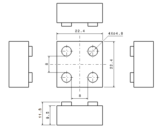
The dimension of 15.7 given by you is wrong. So I have updated it to 22.4 as required.
Add Answer to:
Draw the front, top, and bottom views Add sufficient dimensions to fully define the geometry Mode...
Given: The front and top views of an object. Required: Draw the right side view and...
 Given: The front and top views of an object.
Required: Draw the right side view and complete the bottom half
as instructed.
For part 2: Draw the right side view of surface
14,17,19,20,26.
ORTHOGRAPHIC READING GIVEN: The front and top views of an object. 10 REQUIRED: Draw the right side view and complete the bottom half as instructed. 13 14 15 16 17 18. 26 20 22 Draw the right side view of surface 14,17,19,20,26. 14 26
Given: The front and top views of an object.
Required: Draw the right side view and complete the bottom half
as instructed.
For part 2: Draw the right side view of surface
14,17,19,20,26.
ORTHOGRAPHIC READING GIVEN: The front and top views of an object. 10 REQUIRED: Draw the right side view and complete the bottom half as instructed. 13 14 15 16 17 18. 26 20 22 Draw the right side view of surface 14,17,19,20,26. 14 26
Please drawing the front view, top view and side view of this drafing tools. + on the top view, d...
 Please drawing the front view, top view and side view of this
drafing tools.
+ on the top view, draw a cutting plane AA’ to draw a section
view please.
+ Please drawing the isometric Pictorial drawing also.
Thank you!
t 1305-FINAL PROJECT B" You are showed a machined part, and you are to messure that part using e caliper Then you wil ransfer the neasurement into hand drawings with drafting tooks that you will be creating # for the...
Please drawing the front view, top view and side view of this
drafing tools.
+ on the top view, draw a cutting plane AA’ to draw a section
view please.
+ Please drawing the isometric Pictorial drawing also.
Thank you!
t 1305-FINAL PROJECT B" You are showed a machined part, and you are to messure that part using e caliper Then you wil ransfer the neasurement into hand drawings with drafting tooks that you will be creating # for the...
 Given: The front and top views of an object.
Required: Draw the right side view and complete the bottom half
as instructed.
For part 2: Draw the right side view of surface
14,17,19,20,26.
ORTHOGRAPHIC READING GIVEN: The front and top views of an object. 10 REQUIRED: Draw the right side view and complete the bottom half as instructed. 13 14 15 16 17 18. 26 20 22 Draw the right side view of surface 14,17,19,20,26. 14 26
Given: The front and top views of an object.
Required: Draw the right side view and complete the bottom half
as instructed.
For part 2: Draw the right side view of surface
14,17,19,20,26.
ORTHOGRAPHIC READING GIVEN: The front and top views of an object. 10 REQUIRED: Draw the right side view and complete the bottom half as instructed. 13 14 15 16 17 18. 26 20 22 Draw the right side view of surface 14,17,19,20,26. 14 26
 Please drawing the front view, top view and side view of this
drafing tools.
+ on the top view, draw a cutting plane AA’ to draw a section
view please.
+ Please drawing the isometric Pictorial drawing also.
Thank you!
t 1305-FINAL PROJECT B" You are showed a machined part, and you are to messure that part using e caliper Then you wil ransfer the neasurement into hand drawings with drafting tooks that you will be creating # for the...
Please drawing the front view, top view and side view of this
drafing tools.
+ on the top view, draw a cutting plane AA’ to draw a section
view please.
+ Please drawing the isometric Pictorial drawing also.
Thank you!
t 1305-FINAL PROJECT B" You are showed a machined part, and you are to messure that part using e caliper Then you wil ransfer the neasurement into hand drawings with drafting tooks that you will be creating # for the...
Most questions answered within 3 hours.
-
`1) How is -9 (base 10) represented in 8-bit two's complement
notation?
a) 00001001
b)11110111
c)11110110...
asked 6 minutes ago -
A 10.000 g sample of water contains 11.19% H by mass. what
should be the %H...
asked 23 minutes ago -
Consider an investment game among 2 players. Each player can
either invest,
i, or not invest,-i....
asked 21 minutes ago -
The time taken to complete a particular task is normally
distributed with a standard deviation of...
asked 31 minutes ago -
we have heteroskedasticity in a regression when:
When the variance of error terms changes when an...
asked 40 minutes ago -
Explain some different types of fungi. State the different
divisions undergo by fungi.
asked 53 minutes ago -
The shortest time that 120 C can flow through a 20 A circuit
breaker without tripping...
asked 54 minutes ago -
A software design pattern is a general, reusable solution to a
commonly occurring problem, acting as...
asked 56 minutes ago -
The mean waiting time at the drive-through of a fast-food
restaurant from the time an order...
asked 1 hour ago -
The pitch (p) of a helix is defined as p = dn, in which n is...
asked 1 hour ago -
Do you agree that the declining stock of social capital is the
blame for the failure...
asked 1 hour ago -
A researcher is interested in whether coffee consumption helps
with performance on reading comprehension tasks. The...
asked 1 hour ago