A pin-connected beam AC shown in Figure is supported by 1.6m of strut BD. The beam is subjected t...
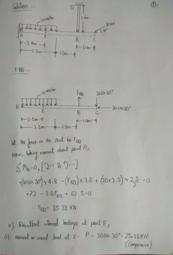
A pin-connected beam AC shown in Figure is supported by 1.6m of strut BD. The beam is subjected to uniformly distributed load of 20 kN/m at 2.5m from A and an inclined concentrated load of 30 KN with 30℃ angle at respectively. The beam has a constant cross-sectional area of Abm = 0.004 m2 and the strut has a constant cross sectional area of Ast = 0.002 m2 respectively. The diameter of all pins is 20 mm.

I. Determine the resultant internal loadings in the beam at point E
Il. Calculate the normal stress acting in the beam at point E
IlI. Calculate the average shear stress in 20 mm diameter of pin at joint A.
IV. If the loads on the beam caused the strut to elongate, determine the vertical displacement of strut. Take Young Modulus of the strut as 200 GPa.
Homework Answers


Add Answer to:
A pin-connected beam AC shown in Figure is supported by 1.6m of strut BD. The beam is subjected t...
Problem 4 (3pts) The beam AB is supported by a single-shear pin connection at joint A...
 Problem 4 (3pts) The beam AB is supported by a single-shear pin connection at joint A and by a double-shear connection to member (1) at joint B. Member (1) is connected to the support at C with a double-shear pin connection. Member (1) has a cross-sectional area of 100 mm and a yield strength of 340 MPa. The pins at A, B, and C each have a diameter of 12 mm, and an ultimate shear strength of 270 MPa. Specifications...
M4.3 Load capacity of beam-strut structure scenes The structure supports a distributed load of w. The...
 M4.3 Load capacity of beam-strut structure scenes The structure supports a distributed load of w. The limiting stress in rod (1) is 330 MPa, and the limiting stress in each pin is 200 MPa. If the minimum factor of safety for the structure is 2.20, determine the maximum distributed load magnitude w that may be applied to the struct the stresses in the rod and pins at the maximum w. 1 m 14-mm-diam. pin e plus double shear 12-mm-diam. rod...
A rectangular beam is subjected to the loadings shown in Figure Q.16(a) has cross section of...
 A rectangular beam is subjected to the loadings shown in Figure Q.16(a) has cross section of 100 mm x 300 mm as shown in Figure Q.16(b). An axial load of 5 kN is applied along the centroid of the cross-section at one end of the beam. Compute the normal stress and shear stress at point P through the cut-section of P in the beam. [15 marks] у 10 kN/m P Ž 5 KN --- 00 P k 3 m -...
Beam AB is supported as shown in the figure. Tie rod (1) has a diameter of...
 Beam AB is supported as shown in the figure. Tie rod (1) has a diameter of 58 mm ,and it is attached at B and Cwith 24 mm diameter double-shear pin connections. The pin connection at A consists of a 40 mm diameter single-shear pin. The pins at A, B, and C each have an ultimate shear strength of 500 MPа ,and tie rod (1) has a yield strength of 280 МРPа . A uniformly distributed load of W is...
The beam has the rectangular cross section shown. A beam of length 6 meters pin-supported 2...
 The beam has the rectangular cross section shown. A beam of
length 6 meters pin-supported 2 meters from the left end and
roller-supported 2 meters from the right end. The beam has a
rectangular cross section with base length 50 millimeters and
height 150 millimeters. Load: w, uniform along beam.
Part A If w = 4 kN/m , determine the maximum bending stress in
the beam.
Can you please draw out the moment and shear diagrams for this
one using...
The beam has the rectangular cross section shown. A beam of
length 6 meters pin-supported 2 meters from the left end and
roller-supported 2 meters from the right end. The beam has a
rectangular cross section with base length 50 millimeters and
height 150 millimeters. Load: w, uniform along beam.
Part A If w = 4 kN/m , determine the maximum bending stress in
the beam.
Can you please draw out the moment and shear diagrams for this
one using...
The rigid bar shown is supported by axial bar (1) and by a pin connection at C. Axial bar (1) has...
 The rigid bar shown is supported by axial bar (1) and by a pin
connection at C. Axial bar (1) has a cross-sectional area
of A1 = 250 mm2, an elastic modulus
of E = 200 GPa, and a coefficient of thermal expansion of
α= 11.3 × 10⁻⁶/°C. The pin at C has a diameter
of 40 mm. After load P has been applied and the
temperature of the entire assembly has been increased by 10°C, the
total strain in...
The rigid bar shown is supported by axial bar (1) and by a pin
connection at C. Axial bar (1) has a cross-sectional area
of A1 = 250 mm2, an elastic modulus
of E = 200 GPa, and a coefficient of thermal expansion of
α= 11.3 × 10⁻⁶/°C. The pin at C has a diameter
of 40 mm. After load P has been applied and the
temperature of the entire assembly has been increased by 10°C, the
total strain in...
Chapter 5, Problem 35P Bookmark Show all steps ON Problem The pin-connected structure shown in Figure...
 Chapter 5, Problem 35P Bookmark Show all steps ON Problem The pin-connected structure shown in Figure P5.35/36 consists of a rigid beam ABCD and two supporting bars. Bar (1) is a bronze alloy [E105 GPa] with a cross-sectional area of A1 290 mm2. Bar (2) is an aluminum alloy [E70 GPa] with a cross-sectional area of A2 650 mm2. If a load of P 30 kN is applied at B, determine (a) the normal stresses in both bars (1) and...
4. The beam AC shown in Figure 4 is supported by two columns AE and BD,...
 4. The beam AC shown in Figure 4 is supported by two columns AE and BD, and carries a load P (P-50 kN). The columns have the same square cross section hxh, Young's modulus E 2x10⁵ MPa. Determine the minimum dimension h of the cross section such that both columns do not fail in elastic buckling. Use the factor of safety of 1.2 against buckling. Pin connections are used for ends E, A, and B as shown in Figure 4....
A 3 m rigid bar AB is supported with a vertical translational spring at A and a pin at B The bar is subjected to a linearly varying distributed load with maximum intensity g Calculate the ver...
 A 3 m rigid bar AB is supported with a vertical translational spring at A and a pin at B The bar is subjected to a linearly varying distributed load with maximum intensity g Calculate the vertical deformation of the spring if the spring constant is 700 kN/m. (ans: 21.43 mm) 2. A steel cable with a nominal diameter of 25 mm is used in a construction yard to lift a bridge section weighing 38 kN. The cable has an...
P1.12 A simple pin-connected truss is loaded and supported as shown in Figure P1.12. The load...
 P1.12 A simple pin-connected truss is loaded and supported as shown in Figure P1.12. The load P is 200 kN. All members of the truss are aluminum pipes that have an outside diameter of 115 mm and a wall thickness of 6 mm. Determine the normal stress in each truss member. Assume truss dimensions of a-12.0 m, b - 7.5 m, and c 6.0 m. FIGURE P1.12
 Problem 4 (3pts) The beam AB is supported by a single-shear pin connection at joint A and by a double-shear connection to member (1) at joint B. Member (1) is connected to the support at C with a double-shear pin connection. Member (1) has a cross-sectional area of 100 mm and a yield strength of 340 MPa. The pins at A, B, and C each have a diameter of 12 mm, and an ultimate shear strength of 270 MPa. Specifications...
 M4.3 Load capacity of beam-strut structure scenes The structure supports a distributed load of w. The limiting stress in rod (1) is 330 MPa, and the limiting stress in each pin is 200 MPa. If the minimum factor of safety for the structure is 2.20, determine the maximum distributed load magnitude w that may be applied to the struct the stresses in the rod and pins at the maximum w. 1 m 14-mm-diam. pin e plus double shear 12-mm-diam. rod...
 A rectangular beam is subjected to the loadings shown in Figure Q.16(a) has cross section of 100 mm x 300 mm as shown in Figure Q.16(b). An axial load of 5 kN is applied along the centroid of the cross-section at one end of the beam. Compute the normal stress and shear stress at point P through the cut-section of P in the beam. [15 marks] у 10 kN/m P Ž 5 KN --- 00 P k 3 m -...
 Beam AB is supported as shown in the figure. Tie rod (1) has a diameter of 58 mm ,and it is attached at B and Cwith 24 mm diameter double-shear pin connections. The pin connection at A consists of a 40 mm diameter single-shear pin. The pins at A, B, and C each have an ultimate shear strength of 500 MPа ,and tie rod (1) has a yield strength of 280 МРPа . A uniformly distributed load of W is...
 The beam has the rectangular cross section shown. A beam of
length 6 meters pin-supported 2 meters from the left end and
roller-supported 2 meters from the right end. The beam has a
rectangular cross section with base length 50 millimeters and
height 150 millimeters. Load: w, uniform along beam.
Part A If w = 4 kN/m , determine the maximum bending stress in
the beam.
Can you please draw out the moment and shear diagrams for this
one using...
The beam has the rectangular cross section shown. A beam of
length 6 meters pin-supported 2 meters from the left end and
roller-supported 2 meters from the right end. The beam has a
rectangular cross section with base length 50 millimeters and
height 150 millimeters. Load: w, uniform along beam.
Part A If w = 4 kN/m , determine the maximum bending stress in
the beam.
Can you please draw out the moment and shear diagrams for this
one using...
 The rigid bar shown is supported by axial bar (1) and by a pin
connection at C. Axial bar (1) has a cross-sectional area
of A1 = 250 mm2, an elastic modulus
of E = 200 GPa, and a coefficient of thermal expansion of
α= 11.3 × 10⁻⁶/°C. The pin at C has a diameter
of 40 mm. After load P has been applied and the
temperature of the entire assembly has been increased by 10°C, the
total strain in...
The rigid bar shown is supported by axial bar (1) and by a pin
connection at C. Axial bar (1) has a cross-sectional area
of A1 = 250 mm2, an elastic modulus
of E = 200 GPa, and a coefficient of thermal expansion of
α= 11.3 × 10⁻⁶/°C. The pin at C has a diameter
of 40 mm. After load P has been applied and the
temperature of the entire assembly has been increased by 10°C, the
total strain in...
 Chapter 5, Problem 35P Bookmark Show all steps ON Problem The pin-connected structure shown in Figure P5.35/36 consists of a rigid beam ABCD and two supporting bars. Bar (1) is a bronze alloy [E105 GPa] with a cross-sectional area of A1 290 mm2. Bar (2) is an aluminum alloy [E70 GPa] with a cross-sectional area of A2 650 mm2. If a load of P 30 kN is applied at B, determine (a) the normal stresses in both bars (1) and...
 4. The beam AC shown in Figure 4 is supported by two columns AE and BD, and carries a load P (P-50 kN). The columns have the same square cross section hxh, Young's modulus E 2x10⁵ MPa. Determine the minimum dimension h of the cross section such that both columns do not fail in elastic buckling. Use the factor of safety of 1.2 against buckling. Pin connections are used for ends E, A, and B as shown in Figure 4....
 A 3 m rigid bar AB is supported with a vertical translational spring at A and a pin at B The bar is subjected to a linearly varying distributed load with maximum intensity g Calculate the vertical deformation of the spring if the spring constant is 700 kN/m. (ans: 21.43 mm) 2. A steel cable with a nominal diameter of 25 mm is used in a construction yard to lift a bridge section weighing 38 kN. The cable has an...
 P1.12 A simple pin-connected truss is loaded and supported as shown in Figure P1.12. The load P is 200 kN. All members of the truss are aluminum pipes that have an outside diameter of 115 mm and a wall thickness of 6 mm. Determine the normal stress in each truss member. Assume truss dimensions of a-12.0 m, b - 7.5 m, and c 6.0 m. FIGURE P1.12
Most questions answered within 3 hours.
-
What do the phenomena of overshadowing, the CS preexposure
effect, and relative validity of cues have...
asked 19 minutes ago -
Assuming air has a density of 1.17 g/L and .973 atm what is the
average molar...
asked 12 minutes ago -
A student studying for a vocabulary test knows the meanings of
16 words from a list...
asked 7 minutes ago -
Developmental Biology! Please answer all the questions
7) Mislocalization of oscar to the side of the...
asked 6 minutes ago -
We have two Earths, one as ours and another that is twice
heavier than that of...
asked 15 minutes ago -
At an annual interest rate of 6%, which would you prefer; three
annual year-end cash flows...
asked 14 minutes ago -
1. (40’) In myStack.cpp, implement the member functions of the
class myStack, which is the class...
asked 14 minutes ago -
MnO4^- + C2O4^2- ---->MnO2 +CO3^2- balance in basic media
asked 33 minutes ago -
What is the missing keyword in the program below?
public class Batman {
public static int...
asked 29 minutes ago -
The Southern Oscillation can be best described
as
relative changes between two pressure systems.
variation in...
asked 31 minutes ago -
We predict that learning statistics will increase a student's
IQ. Those not learning statistics have a...
asked 36 minutes ago -
Write a procedure of how you would separate benzoic acid
(acidic), decane (neutral), and adenine (basic)...
asked 36 minutes ago