
Homework Answers
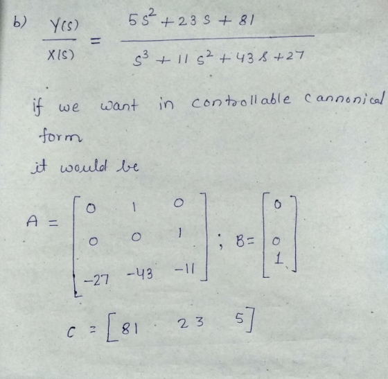
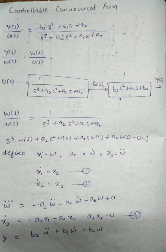
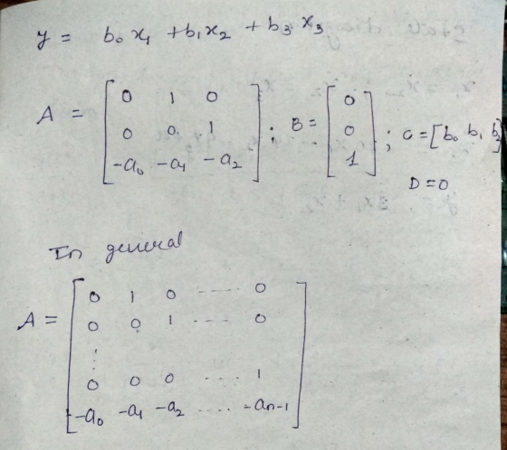
The derivation of getting A, B, C matrices in controllable canonical form is given below
PS: To avoid confusion, the input in the derivation is taken as U(S) as x is chosen as state variable.
Add Answer to:
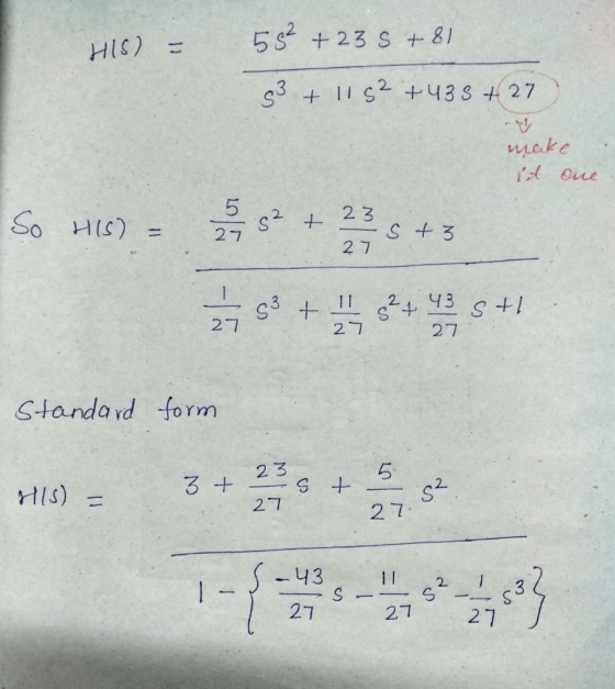
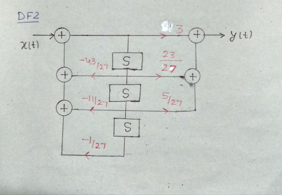
6. For the transfer function 5s2 +23s+81 H(s) = s3 +11s 43s +27 +11 s. (a) Sketch the DF2 (canoni...
10. Consider the following input-output transfer function. U(s) s3 6s 11s +4 Draw the CCF state d...
 State space of transfer function
10. Consider the following input-output transfer function. U(s) s3 6s 11s +4 Draw the CCF state diagram of the system. Obtain the dynamic equations of the system in CCF. i.i Obtain the dynamic equations of the system in odr.
10. Consider the following input-output transfer function. U(s) s3 6s 11s +4 Draw the CCF state diagram of the system. Obtain the dynamic equations of the system in CCF. i.i Obtain the dynamic equations of the...
State space of transfer function
10. Consider the following input-output transfer function. U(s) s3 6s 11s +4 Draw the CCF state diagram of the system. Obtain the dynamic equations of the system in CCF. i.i Obtain the dynamic equations of the system in odr.
10. Consider the following input-output transfer function. U(s) s3 6s 11s +4 Draw the CCF state diagram of the system. Obtain the dynamic equations of the system in CCF. i.i Obtain the dynamic equations of the...
Problem 1: Convert the following transfer function model into state-space model and sketch its block diagram with x defined as the leftmost state variable. 2s2 +8s +6 s3 +8s2 +16s+6 Problem...
 Problem 1: Convert the following transfer function model into state-space model and sketch its block diagram with x defined as the leftmost state variable. 2s2 +8s +6 s3 +8s2 +16s+6
Problem 1: Convert the following transfer function model into state-space model and sketch its block diagram with x defined as the leftmost state variable. 2s2 +8s +6 s3 +8s2 +16s+6
Problem 1: Convert the following transfer function model into state-space model and sketch its block diagram with x defined as the leftmost state variable. 2s2 +8s +6 s3 +8s2 +16s+6
S+5 Consider a system where the transfer function is given as: G(s) -tS 3+6s2+11s+6 a. Sketch a r...
 s+5 Consider a system where the transfer function is given as: G(s) -tS 3+6s2+11s+6 a. Sketch a root locus for static controller gain K b. Design a controller to meet the following specifictions: t, S 1s, 2 0.6, e(oo)Istep0
s+5 Consider a system where the transfer function is given as: G(s) -tS 3+6s2+11s+6 a. Sketch a root locus for static controller gain K b. Design a controller to meet the following specifictions: t, S 1s, 2 0.6, e(oo)Istep0
s+5 Consider a system where the transfer function is given as: G(s) -tS 3+6s2+11s+6 a. Sketch a root locus for static controller gain K b. Design a controller to meet the following specifictions: t, S 1s, 2 0.6, e(oo)Istep0
4. Block Diagrams (a) Consider a causal LTI system with transfer function H(s)2 Show the direct-form block diagram of Hi(s) (b) Consider a causal LTI system with transfer function 2s2 +4s -6 H(s)- Sh...
 4. Block Diagrams (a) Consider a causal LTI system with transfer function H(s)2 Show the direct-form block diagram of Hi(s) (b) Consider a causal LTI system with transfer function 2s2 +4s -6 H(s)- Show the direct-form block diagram of Hi(s) c) Now observe that to draw a block diagram as a cascaded combination of two 1st order subsystems. d) Finally, use partial fraction expansion to express this system as a sum of individual poles and observe that you can draw...
100 H(s) 2. For the transfer function: s3+32s2260s+400 a) create a reduced order model by removing...
 100 H(s) 2. For the transfer function: s3+32s2260s+400 a) create a reduced order model by removing the "high frequency" pole (Hints ... Use zpk() to find poles. Make sure the new transfer function has the same Kdc as the original model) b) Use MatLab to verify that the step response for the two models are "equivalent"
Select the correct transfer function for the block diagram below: R(s) C(s) C(s) R(s) s3+13s2+32s+(20s+k) C(s)...
 Select the correct transfer function for the block diagram below: R(s) C(s) C(s) R(s) s3+13s2+32s+(20s+k) C(s) R(s) s3+13s2+32s+(20+k) b. C(s) R(s) s3+13s2+(32+k)s+(20+k) R(s) C(s) s3+13s2+20s+32 d.
5) (10 pts) The transfer function of a system is given by: S +1 H(s) =...
 5) (10 pts) The transfer function of a system is given by: S +1 H(s) = $3+ 9s2 + 23s + 15 What is the steady state error of this system when the input is unit step function?
4. Block Diagrams (a) Consider a causal LTI system with transfer function Show the direct-form block diagram of Hi(s) b) Consider a causal LTI system with transfer function H282+4s -6 H (s) = 2 Show...
 4. Block Diagrams (a) Consider a causal LTI system with transfer function Show the direct-form block diagram of Hi(s) b) Consider a causal LTI system with transfer function H282+4s -6 H (s) = 2 Show the direct-form block diagram of Hi(s) (c) Now observe that to draw a block diagram as a cascaded combination of two 1st order subsystems. (d) Finally, use partial fraction expansion to express this system as a sum of individual poles and observe that you can...
27. (a) The circuit below has transfer function H(s)--out . It is known that L =0.5...
 27. (a) The circuit below has transfer function H(s)--out . It is known that L =0.5 H ist andRI = 4 Ω and R2=2Q. (i) Compute the transfer function. (ii) Compute the COMPLETE range of for which the circuit is BIBO stable. R2 out C : 0.25 F. Compute H(s)-out ) Determ ne the complete range of m for which Vin(s) (b) Let R= 2 Ω the circuit is BIBO stable in out mvtt) out
singal and system QUESTION 5 [20 marks] Given transfer function of a networks H(s) transfer function...
 singal and
system
QUESTION 5 [20 marks] Given transfer function of a networks H(s) transfer function at w = 1000 rad/s. $10+ 52 +10005+7x10⁶ - Evaluate the [10 marks) b) Simplify and obtain the frequency response (magnitude and phase plots) of the 100(5+10) following transfer function H(s) s+10000 [6 marks] Sketch the magnitude and phase plots from (b) using Bode Plot Technique. [4 marks]
singal and
system
QUESTION 5 [20 marks] Given transfer function of a networks H(s) transfer function at w = 1000 rad/s. $10+ 52 +10005+7x10⁶ - Evaluate the [10 marks) b) Simplify and obtain the frequency response (magnitude and phase plots) of the 100(5+10) following transfer function H(s) s+10000 [6 marks] Sketch the magnitude and phase plots from (b) using Bode Plot Technique. [4 marks]
 State space of transfer function
10. Consider the following input-output transfer function. U(s) s3 6s 11s +4 Draw the CCF state diagram of the system. Obtain the dynamic equations of the system in CCF. i.i Obtain the dynamic equations of the system in odr.
10. Consider the following input-output transfer function. U(s) s3 6s 11s +4 Draw the CCF state diagram of the system. Obtain the dynamic equations of the system in CCF. i.i Obtain the dynamic equations of the...
State space of transfer function
10. Consider the following input-output transfer function. U(s) s3 6s 11s +4 Draw the CCF state diagram of the system. Obtain the dynamic equations of the system in CCF. i.i Obtain the dynamic equations of the system in odr.
10. Consider the following input-output transfer function. U(s) s3 6s 11s +4 Draw the CCF state diagram of the system. Obtain the dynamic equations of the system in CCF. i.i Obtain the dynamic equations of the...
 Problem 1: Convert the following transfer function model into state-space model and sketch its block diagram with x defined as the leftmost state variable. 2s2 +8s +6 s3 +8s2 +16s+6
Problem 1: Convert the following transfer function model into state-space model and sketch its block diagram with x defined as the leftmost state variable. 2s2 +8s +6 s3 +8s2 +16s+6
Problem 1: Convert the following transfer function model into state-space model and sketch its block diagram with x defined as the leftmost state variable. 2s2 +8s +6 s3 +8s2 +16s+6
 s+5 Consider a system where the transfer function is given as: G(s) -tS 3+6s2+11s+6 a. Sketch a root locus for static controller gain K b. Design a controller to meet the following specifictions: t, S 1s, 2 0.6, e(oo)Istep0
s+5 Consider a system where the transfer function is given as: G(s) -tS 3+6s2+11s+6 a. Sketch a root locus for static controller gain K b. Design a controller to meet the following specifictions: t, S 1s, 2 0.6, e(oo)Istep0
s+5 Consider a system where the transfer function is given as: G(s) -tS 3+6s2+11s+6 a. Sketch a root locus for static controller gain K b. Design a controller to meet the following specifictions: t, S 1s, 2 0.6, e(oo)Istep0
 4. Block Diagrams (a) Consider a causal LTI system with transfer function H(s)2 Show the direct-form block diagram of Hi(s) (b) Consider a causal LTI system with transfer function 2s2 +4s -6 H(s)- Show the direct-form block diagram of Hi(s) c) Now observe that to draw a block diagram as a cascaded combination of two 1st order subsystems. d) Finally, use partial fraction expansion to express this system as a sum of individual poles and observe that you can draw...
 100 H(s) 2. For the transfer function: s3+32s2260s+400 a) create a reduced order model by removing the "high frequency" pole (Hints ... Use zpk() to find poles. Make sure the new transfer function has the same Kdc as the original model) b) Use MatLab to verify that the step response for the two models are "equivalent"
 Select the correct transfer function for the block diagram below: R(s) C(s) C(s) R(s) s3+13s2+32s+(20s+k) C(s) R(s) s3+13s2+32s+(20+k) b. C(s) R(s) s3+13s2+(32+k)s+(20+k) R(s) C(s) s3+13s2+20s+32 d.
 5) (10 pts) The transfer function of a system is given by: S +1 H(s) = $3+ 9s2 + 23s + 15 What is the steady state error of this system when the input is unit step function?
 4. Block Diagrams (a) Consider a causal LTI system with transfer function Show the direct-form block diagram of Hi(s) b) Consider a causal LTI system with transfer function H282+4s -6 H (s) = 2 Show the direct-form block diagram of Hi(s) (c) Now observe that to draw a block diagram as a cascaded combination of two 1st order subsystems. (d) Finally, use partial fraction expansion to express this system as a sum of individual poles and observe that you can...
 27. (a) The circuit below has transfer function H(s)--out . It is known that L =0.5 H ist andRI = 4 Ω and R2=2Q. (i) Compute the transfer function. (ii) Compute the COMPLETE range of for which the circuit is BIBO stable. R2 out C : 0.25 F. Compute H(s)-out ) Determ ne the complete range of m for which Vin(s) (b) Let R= 2 Ω the circuit is BIBO stable in out mvtt) out
 singal and
system
QUESTION 5 [20 marks] Given transfer function of a networks H(s) transfer function at w = 1000 rad/s. $10+ 52 +10005+7x10⁶ - Evaluate the [10 marks) b) Simplify and obtain the frequency response (magnitude and phase plots) of the 100(5+10) following transfer function H(s) s+10000 [6 marks] Sketch the magnitude and phase plots from (b) using Bode Plot Technique. [4 marks]
singal and
system
QUESTION 5 [20 marks] Given transfer function of a networks H(s) transfer function at w = 1000 rad/s. $10+ 52 +10005+7x10⁶ - Evaluate the [10 marks) b) Simplify and obtain the frequency response (magnitude and phase plots) of the 100(5+10) following transfer function H(s) s+10000 [6 marks] Sketch the magnitude and phase plots from (b) using Bode Plot Technique. [4 marks]
Most questions answered within 3 hours.
-
The outstanding bonds of Alpha Extracts have a yield to maturity
of 7.4 percent and a...
asked 19 minutes ago -
A 8.15- g bullet from a 9-mm pistol has a velocity of 366.0 m/s.
It strikes...
asked 23 minutes ago -
The Problem: The Case of the Harmonizing Vacations
Your CEO is exploring partnering with a European...
asked 1 hour ago -
A chemical equation is balanced by adding coefficients in front
of some formulas so that the...
asked 1 hour ago -
From the literature (reference your sources): What are the
lattice parameters of calcite and aragonite? Why...
asked 2 hours ago -
Your system is rejecting the question am asking which is
preceded by a case study. It...
asked 2 hours ago -
3. On January 2, 2000, Larry creates a trust with himself as
trustee. Larry as trustee...
asked 2 hours ago -
A member of the volleyball team spikes the ball. During this
process, she changes the velocity...
asked 2 hours ago -
Are adult gamers less likely to use a gaming console (Xbox,
PlayStation, Wii, etc...) than teen...
asked 3 hours ago -
The University of
Texas recently reported that 43% of college students aged 18-24
would spend their...
asked 3 hours ago -
The length of stay at a specific emergency department in
Phoenix, Arizona, in 2009 had a...
asked 2 hours ago -
. Please give the mechanism for this type of problem. Step by
Step
The toxin that...
asked 2 hours ago