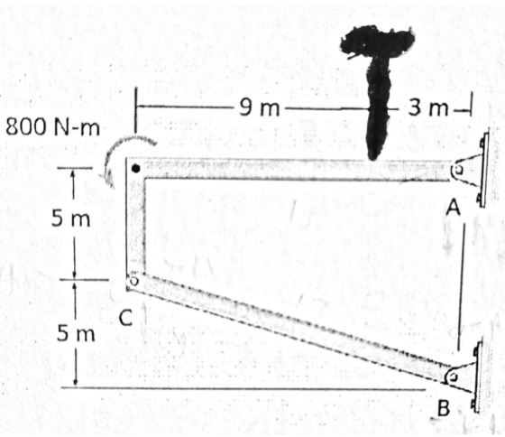
3. Consider following frame:
a. Set up formulas to calculate external reactions at A and B. Obtain values of F(Ax) and F(Bx).
b. Draw free body diagram of member AC and calculate values of F(Ax), F(Cx), and F(Cy).
c. Draw free body diagram of member BC. If problem is solved right, this diagram should be balanced.
Homework Answers


Add Answer to:
3. Consider following frame: a. Set up formulas to calculate external reactions at A and B. Obtai...
3. For the frame shown in Fig. 3, (a) (7%) determine the support reactions, (b) (6%) draw the fre...
 3. For the frame shown in Fig. 3, (a) (7%) determine the support reactions, (b) (6%) draw the free-body diagrams of member AB and member CBD; (c) (12%) replace the loading on the frame by a single resultant force, and specify where its line of action intersects member CD, measured from end C 150 N 500 N 3 m 3m 2 m 400 N -m 0.35 m 0.35 m 3 m 500 N 35° Fig. 3 Fig. 2 Fig. 1...
PlOBlem 4 (10 points) 2 m 3 m The frame is made up of members ACE, BCD and DE. The frame is pin- 6 m supported at A...
 PlOBlem 4 (10 points) 2 m 3 m The frame is made up of members ACE, BCD and DE. The frame is pin- 6 m supported at A and roller-supported at B. On member ACE, determine the 2 m magnitudes and directions of forces acting at pins C and E Hint: Begin with overall free body 3 m diagram 600 N 5 m
PlOBlem 4 (10 points) 2 m 3 m The frame is made up of members ACE, BCD...
PlOBlem 4 (10 points) 2 m 3 m The frame is made up of members ACE, BCD and DE. The frame is pin- 6 m supported at A and roller-supported at B. On member ACE, determine the 2 m magnitudes and directions of forces acting at pins C and E Hint: Begin with overall free body 3 m diagram 600 N 5 m
PlOBlem 4 (10 points) 2 m 3 m The frame is made up of members ACE, BCD...
1) Check stability and determinacy of the structure 2) draw free body diagram 3) determine reactions...
 1) Check stability and determinacy of the structure
2) draw free body diagram
3) determine reactions
4) draw shear diagram
- correct values
- correct shape
- location of the maximum moment on member BC
5) draw moment diagram
- correct values
- correct shape
- location of the maximum moment on member BC
6) draw deformation shape
1) Check stability and determinacy of the structure
2) draw free body diagram
3) determine reactions
4) draw shear diagram
- correct values
- correct shape
- location of the maximum moment on member BC
5) draw moment diagram
- correct values
- correct shape
- location of the maximum moment on member BC
6) draw deformation shape
A uniform, 24.5 kg beam of length 2.90 m is hanging horizontally as shown in the...
 A uniform, 24.5 kg beam of length 2.90 m is hanging horizontally
as shown in the diagram below. It is pinned to a vertical wall at
point B and supported by a uniform 15.9 kg diagonal brace that is
pinned at point C on the beam and at point A on the
wall. [Use g = 9.80 m/s2.]
There is a load W, with a weight of 211 N, hanging at the end of
the horizontal beam. The distance BC is...
A uniform, 24.5 kg beam of length 2.90 m is hanging horizontally
as shown in the diagram below. It is pinned to a vertical wall at
point B and supported by a uniform 15.9 kg diagonal brace that is
pinned at point C on the beam and at point A on the
wall. [Use g = 9.80 m/s2.]
There is a load W, with a weight of 211 N, hanging at the end of
the horizontal beam. The distance BC is...
The force F is equal to 213 lbs please solve as fast as you can i will rate. Determine the magnitue and direction of the reactions of the external posts such as Ax and Ay and Bx and By as well as the...
 The force F is equal to 213 lbs please solve as fast as you
can i will rate. Determine the magnitue and direction of the
reactions of the external posts such as Ax and Ay and Bx and By as
well as the internal hinges N1 V1 and M1
Figure 1-Frame 10 N/m 5 N/m Parabola 3 m 6 m 10 N/m 8 m 9 m 4 m 4 m
Figure 1-Frame 10 N/m 5 N/m Parabola 3 m 6...
The force F is equal to 213 lbs please solve as fast as you
can i will rate. Determine the magnitue and direction of the
reactions of the external posts such as Ax and Ay and Bx and By as
well as the internal hinges N1 V1 and M1
Figure 1-Frame 10 N/m 5 N/m Parabola 3 m 6 m 10 N/m 8 m 9 m 4 m 4 m
Figure 1-Frame 10 N/m 5 N/m Parabola 3 m 6...
3. Using the image and the following information, determine the support reactions of the frame shown...
 3. Using the image and the following information, determine the support reactions of the frame shown below. a. The members of the frame are shown in black. There are 3 members in the frame (AC, CE, and EF). b. The red dots represent the connection points for the frame. C. The external forces are shown by the blue lines. d. There is a pin support at A and rocker supports at B, D, and F. 250 N 100 N/m 175...
5) ( 40 /oints) Consider the system shown below The weight orali other olycs is nedpble...
 5) ( 40 /oints) Consider the system shown below The weight orali other olycs is nedpble Draw free body diagrams of all the objects in the system and Label them Follow the rules we've leamest in slass in rcgarding which obiects should be drawn and what to includs Includo free boty diagram of the whole frame You do NOT need to include dimensions or angles on your free body diagrams. With cach free body diagram, construct all equations noeded to...
blem #5 (20 pts): for the frame structure shown below, calculate the following a) Support reactions...
 blem #5 (20 pts): for the frame structure shown below, calculate the following a) Support reactions at roller support A and pin support C b) The internal forces at support A. c) The internal forces at point D, which is located at 5 ft from the point A, along the member AB. d) The internal forces at point E, which is located at 4 ft from point C, along the member BC. Note that point D and E are not...
A spring of stiffness k = 200 N/m is mounted against the 10 kg block. The...
 A spring of stiffness k = 200 N/m is mounted against the 10 kg block. The block is subject to the force of F-800 N. When s - O the block is at rest and the spring is uncompressed. The contact surface kinetic friction is uk = 0.25. 1) In the box provided draw the complete free body diagram of the external forces acting on the block. Include all known values, calculated values, and equations for unknowns. Express all forces...
For the frame shown below: 1- Calculate the reactions at the supports. 2- Draw the Normal force, the Shear force and the Bending moment diagrams. Indicate all critical values 3- Show the equilibrium a...
 For the frame shown below:1- Calculate the reactions at the supports.2- Draw the Normal force, the Shear force and the Bending moment
diagrams. Indicate all critical values3- Show the equilibrium at node B.4- Develop the analytical expression for the normal force, the
shear force and the bending moment diagram for memberBC.The 4 Kips/ft load is applied perpendicular to member
AB.
For the frame shown below:1- Calculate the reactions at the supports.2- Draw the Normal force, the Shear force and the Bending moment
diagrams. Indicate all critical values3- Show the equilibrium at node B.4- Develop the analytical expression for the normal force, the
shear force and the bending moment diagram for memberBC.The 4 Kips/ft load is applied perpendicular to member
AB.
 3. For the frame shown in Fig. 3, (a) (7%) determine the support reactions, (b) (6%) draw the free-body diagrams of member AB and member CBD; (c) (12%) replace the loading on the frame by a single resultant force, and specify where its line of action intersects member CD, measured from end C 150 N 500 N 3 m 3m 2 m 400 N -m 0.35 m 0.35 m 3 m 500 N 35° Fig. 3 Fig. 2 Fig. 1...
 PlOBlem 4 (10 points) 2 m 3 m The frame is made up of members ACE, BCD and DE. The frame is pin- 6 m supported at A and roller-supported at B. On member ACE, determine the 2 m magnitudes and directions of forces acting at pins C and E Hint: Begin with overall free body 3 m diagram 600 N 5 m
PlOBlem 4 (10 points) 2 m 3 m The frame is made up of members ACE, BCD...
PlOBlem 4 (10 points) 2 m 3 m The frame is made up of members ACE, BCD and DE. The frame is pin- 6 m supported at A and roller-supported at B. On member ACE, determine the 2 m magnitudes and directions of forces acting at pins C and E Hint: Begin with overall free body 3 m diagram 600 N 5 m
PlOBlem 4 (10 points) 2 m 3 m The frame is made up of members ACE, BCD...
 1) Check stability and determinacy of the structure
2) draw free body diagram
3) determine reactions
4) draw shear diagram
- correct values
- correct shape
- location of the maximum moment on member BC
5) draw moment diagram
- correct values
- correct shape
- location of the maximum moment on member BC
6) draw deformation shape
1) Check stability and determinacy of the structure
2) draw free body diagram
3) determine reactions
4) draw shear diagram
- correct values
- correct shape
- location of the maximum moment on member BC
5) draw moment diagram
- correct values
- correct shape
- location of the maximum moment on member BC
6) draw deformation shape
 A uniform, 24.5 kg beam of length 2.90 m is hanging horizontally
as shown in the diagram below. It is pinned to a vertical wall at
point B and supported by a uniform 15.9 kg diagonal brace that is
pinned at point C on the beam and at point A on the
wall. [Use g = 9.80 m/s2.]
There is a load W, with a weight of 211 N, hanging at the end of
the horizontal beam. The distance BC is...
A uniform, 24.5 kg beam of length 2.90 m is hanging horizontally
as shown in the diagram below. It is pinned to a vertical wall at
point B and supported by a uniform 15.9 kg diagonal brace that is
pinned at point C on the beam and at point A on the
wall. [Use g = 9.80 m/s2.]
There is a load W, with a weight of 211 N, hanging at the end of
the horizontal beam. The distance BC is...
 The force F is equal to 213 lbs please solve as fast as you
can i will rate. Determine the magnitue and direction of the
reactions of the external posts such as Ax and Ay and Bx and By as
well as the internal hinges N1 V1 and M1
Figure 1-Frame 10 N/m 5 N/m Parabola 3 m 6 m 10 N/m 8 m 9 m 4 m 4 m
Figure 1-Frame 10 N/m 5 N/m Parabola 3 m 6...
The force F is equal to 213 lbs please solve as fast as you
can i will rate. Determine the magnitue and direction of the
reactions of the external posts such as Ax and Ay and Bx and By as
well as the internal hinges N1 V1 and M1
Figure 1-Frame 10 N/m 5 N/m Parabola 3 m 6 m 10 N/m 8 m 9 m 4 m 4 m
Figure 1-Frame 10 N/m 5 N/m Parabola 3 m 6...
 3. Using the image and the following information, determine the support reactions of the frame shown below. a. The members of the frame are shown in black. There are 3 members in the frame (AC, CE, and EF). b. The red dots represent the connection points for the frame. C. The external forces are shown by the blue lines. d. There is a pin support at A and rocker supports at B, D, and F. 250 N 100 N/m 175...
 5) ( 40 /oints) Consider the system shown below The weight orali other olycs is nedpble Draw free body diagrams of all the objects in the system and Label them Follow the rules we've leamest in slass in rcgarding which obiects should be drawn and what to includs Includo free boty diagram of the whole frame You do NOT need to include dimensions or angles on your free body diagrams. With cach free body diagram, construct all equations noeded to...
 blem #5 (20 pts): for the frame structure shown below, calculate the following a) Support reactions at roller support A and pin support C b) The internal forces at support A. c) The internal forces at point D, which is located at 5 ft from the point A, along the member AB. d) The internal forces at point E, which is located at 4 ft from point C, along the member BC. Note that point D and E are not...
 A spring of stiffness k = 200 N/m is mounted against the 10 kg block. The block is subject to the force of F-800 N. When s - O the block is at rest and the spring is uncompressed. The contact surface kinetic friction is uk = 0.25. 1) In the box provided draw the complete free body diagram of the external forces acting on the block. Include all known values, calculated values, and equations for unknowns. Express all forces...
 For the frame shown below:1- Calculate the reactions at the supports.2- Draw the Normal force, the Shear force and the Bending moment
diagrams. Indicate all critical values3- Show the equilibrium at node B.4- Develop the analytical expression for the normal force, the
shear force and the bending moment diagram for memberBC.The 4 Kips/ft load is applied perpendicular to member
AB.
For the frame shown below:1- Calculate the reactions at the supports.2- Draw the Normal force, the Shear force and the Bending moment
diagrams. Indicate all critical values3- Show the equilibrium at node B.4- Develop the analytical expression for the normal force, the
shear force and the bending moment diagram for memberBC.The 4 Kips/ft load is applied perpendicular to member
AB.
Most questions answered within 3 hours.
-
Work of 1950 J is done by stirring a perfectly insulated beaker
containing 75 g of...
asked 26 minutes ago -
The neighborhood kids set up an outdoor lemonade stand in
Maryland in June. They find that...
asked 27 minutes ago -
9. A company has a beginning inventory of 4,000 units. The
company estimates it will sell...
asked 41 minutes ago -
A patient goes to the doctor's office with symptoms of a urinary
tract infection and provides...
asked 43 minutes ago -
When responding to the essay questions, be sure to cite any
material you obtained from a...
asked 43 minutes ago -
The energy of an electron in a 2.25-eV-deep potential well is
1.50 eV.At what distance into...
asked 45 minutes ago -
Q1:Which three evolutionary innovations are present in land
plants (but not all land plants) that allowed...
asked 47 minutes ago -
Lymphosarcoma is
extremely rare. Risk factors for the disease are largely unknown.
What kind of study...
asked 50 minutes ago -
The solubility of benzoic acid in water is:
0.29g/100mL at 20°C
6.8g/100mL at 100°C
a) What...
asked 51 minutes ago -
Which food law was passed in 1996 and changed how pesticide
residues on food were regulated...
asked 1 hour ago -
companies either hire outside programmers to
write_____ software or use their own internal developers.
asked 1 hour ago -
A magnetic dipole m(t) = m_0*cos(ωt) can be
described as current density j(r,t) = −cm(t) ×...
asked 1 hour ago