
Homework Answers
b)) response
Add Answer to:
Problem 3 Use the 1-DOF EOM at the right to complete this problem. The EOM describes a damped sys...
show the codes Problem:3 Use the 1-DOF EOM at the right to complete this problem. The EOM describes a damped system that is being impacted by a force Fh-300N over a period of Δt-0.01s. Note th...
 show the codes
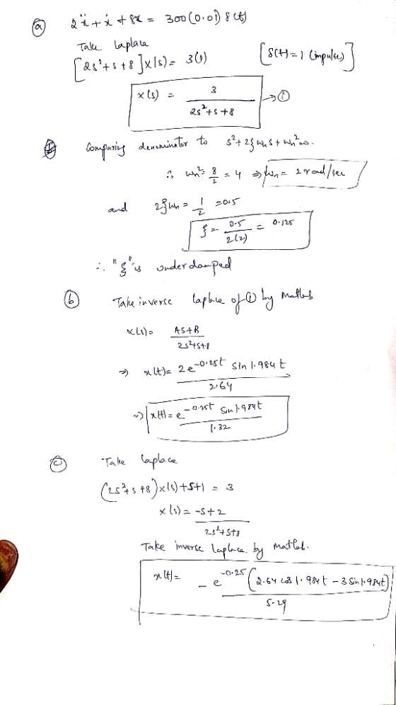
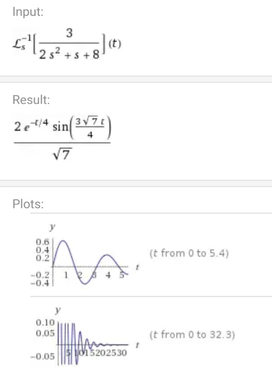
Problem:3 Use the 1-DOF EOM at the right to complete this problem. The EOM describes a damped system that is being impacted by a force Fh-300N over a period of Δt-0.01s. Note that δ(t) represents the unit impulse r is measured in meters. a. Verify that the system is underdamped b. For zero initial conditions (ro-zo = 0), what is the total response z(t)? Plot the response in MATLAB c. For xo =-1 mi and ro =...
show the codes
Problem:3 Use the 1-DOF EOM at the right to complete this problem. The EOM describes a damped system that is being impacted by a force Fh-300N over a period of Δt-0.01s. Note that δ(t) represents the unit impulse r is measured in meters. a. Verify that the system is underdamped b. For zero initial conditions (ro-zo = 0), what is the total response z(t)? Plot the response in MATLAB c. For xo =-1 mi and ro =...
Use the 1-DOF EOM at the right to complete this problem. The EOM describes a damped system that is being impacted by a force Fh 300N over a period of Δt-0.01s. Note that δ(t) represents the unit impu...
 Use the 1-DOF EOM at the right to complete this problem. The EOM describes a damped system that is being impacted by a force Fh 300N over a period of Δt-0.01s. Note that δ(t) represents the unit impulse function and z is measured in meters. a. Verify that the system is underdamped. b. For zero initial conditions (ro0), what is the total response (t)? Plot the response in MATLAB. c. For zo1 m and o 0, what is the total...
2. The following ODE model (for the Duffing oscillator) describes the motion of a damped spring d...
 2. The following ODE model (for the Duffing oscillator) describes the motion of a damped spring driven by a periodic force: r(0) = zo (a) Rewrite the second order non-autonomous system in one independent variable above as an autonomous system in three independent variables: x, y and r, where: y-r ano T 1, with T(0)-0 (b) Fix the parameter values of α = 1, β-0, δ 0.05, w-1. Additionally, fix the initial conditions 2(0)-10, z'(0) . For the values of...
7.22 A simple 1-DOF mechanical system has the following transfer function Y(s) 0.25 U(s) s +2s...
 7.22 A simple 1-DOF mechanical system has the following transfer function Y(s) 0.25 U(s) s +2s +9 where the position of the mass y0) is in meters. The system is initially at rest, y(O) (0) 0, and the applied force is a step function u(t0 4N Copyrighto Problems 243 a. Accurately sketch the system response y() and label all important performance criteria on your sketch b. Use MATLAB or Simulink to verify your sketch in part (a). Plot y(o) from...
Problem 1: The impulse response ht) for a particular LTI system is shown below hit) Be5e (4 cos(3...
 Problem 1: The impulse response ht) for a particular LTI system is shown below hit) Be5e (4 cos(3t)+ 6 sin(3t) e. u(t) 1. Plot the impulse response for h(t) directly from the above equation by creating a time vector 2. Use the residue function to determine the transfer function H(s). Determine the locations of the poles and zeros of H(s) with the roots function, and plot them in the s-plane (x for poles, o for zeros). Use the freas function...
Part I: For each problem, there is only one right answer 1. The model of a...
 Part I: For each problem, there is only one right answer 1. The model of a system in the frequency domain is A. the transfer function from the input to the output. B. the differential equation which defines the relation between the input and the output. C. the zero-state response of the system D. None 2. For a system whose input r and output y are related by the differential equation u(0)a30) dr(t) +3r(t) dt dt2 the transfer function from...
Problem # 3 (20 pts.) A) Given For the circuit IL (t) I() (T Let R-2Ω,...
 Problem # 3 (20 pts.) A) Given For the circuit IL (t) I() (T Let R-2Ω, L-05H, C = .05F. Also Vo(0) = 0 Volts, and L(0) = 0 Amps B) Determine 1) The transfer function Vc(s)/I(s) 2) The pole-zero map 3) The response Vo(t) if I(t)-6(t)A (impulse response) 4) The response Vc(t) if l(t)u(t)A (step response) 5) The step response plot using MATLAB (optional) Evaluation Criteria Rubric for Problem # 3 Activities Step 1) Step 2 Step 3) Step...
Problem 2. For the following system described by the difference equation where y[-1-y[-2] = 0 and...
 Problem 2. For the following system described by the difference equation where y[-1-y[-2] = 0 and x[n] = 2u[n]: a. Draw a block diagram of this system using delays, multipliers, and adders b. Determine the impulse response of the system, h[n], and plot it in MATLAB for n = 0, 1, ,20. (Hint: use Euler's Formula to simplify) c. Is this system stable? d. Determine the initial conditioned repsonse, in. e. Find the total response of the system, yn nln....
Problem 1: Let y()- r(t+2)-r(t+1)+r(t)-r(t-1)-u(t-1)-r(t-2)+r(t-3), where r(t) is the ramp function. a) plot y(t) b) plot...
 Problem 1: Let y()- r(t+2)-r(t+1)+r(t)-r(t-1)-u(t-1)-r(t-2)+r(t-3), where r(t) is the ramp function. a) plot y(t) b) plot y'() c) Plot y(2t-3) d) calculate the energy of y(t) note: r(t) = t for t 0 and 0 for t < 0 Problem 2: Let x(t)s u(t)-u(t-2) and y(t) = t[u(t)-u(t-1)] a) b) plot x(t) and y(t) evaluate graphically and plot z(t) = x(t) * y(t) Problem 3: An LTI system has the impulse response h(t) = 5e-tu(t)-16e-2tu(t) + 13e-3t u(t) The input...
1. Given i(t) Cut) Figure 2.1: Step voltage applied to a series RLC circuit. (a) Verify...
 1. Given i(t) Cut) Figure 2.1: Step voltage applied to a series RLC circuit. (a) Verify that the differential equation for v(t) is found as dt2 L dt LC LC (b) If v(0)-5 V and i(0)-OA. find the voltage response, u(t), for t >0 when v, 5V, R#330 n, L-100 mil, C., 0.1uF (c) Now suppose we replace the 5 V source in our circuit with a squarewave as shown below: w(t) Figure 2.2 From the response of v(t) that...
 show the codes
Problem:3 Use the 1-DOF EOM at the right to complete this problem. The EOM describes a damped system that is being impacted by a force Fh-300N over a period of Δt-0.01s. Note that δ(t) represents the unit impulse r is measured in meters. a. Verify that the system is underdamped b. For zero initial conditions (ro-zo = 0), what is the total response z(t)? Plot the response in MATLAB c. For xo =-1 mi and ro =...
show the codes
Problem:3 Use the 1-DOF EOM at the right to complete this problem. The EOM describes a damped system that is being impacted by a force Fh-300N over a period of Δt-0.01s. Note that δ(t) represents the unit impulse r is measured in meters. a. Verify that the system is underdamped b. For zero initial conditions (ro-zo = 0), what is the total response z(t)? Plot the response in MATLAB c. For xo =-1 mi and ro =...
 Use the 1-DOF EOM at the right to complete this problem. The EOM describes a damped system that is being impacted by a force Fh 300N over a period of Δt-0.01s. Note that δ(t) represents the unit impulse function and z is measured in meters. a. Verify that the system is underdamped. b. For zero initial conditions (ro0), what is the total response (t)? Plot the response in MATLAB. c. For zo1 m and o 0, what is the total...
 2. The following ODE model (for the Duffing oscillator) describes the motion of a damped spring driven by a periodic force: r(0) = zo (a) Rewrite the second order non-autonomous system in one independent variable above as an autonomous system in three independent variables: x, y and r, where: y-r ano T 1, with T(0)-0 (b) Fix the parameter values of α = 1, β-0, δ 0.05, w-1. Additionally, fix the initial conditions 2(0)-10, z'(0) . For the values of...
 7.22 A simple 1-DOF mechanical system has the following transfer function Y(s) 0.25 U(s) s +2s +9 where the position of the mass y0) is in meters. The system is initially at rest, y(O) (0) 0, and the applied force is a step function u(t0 4N Copyrighto Problems 243 a. Accurately sketch the system response y() and label all important performance criteria on your sketch b. Use MATLAB or Simulink to verify your sketch in part (a). Plot y(o) from...
 Problem 1: The impulse response ht) for a particular LTI system is shown below hit) Be5e (4 cos(3t)+ 6 sin(3t) e. u(t) 1. Plot the impulse response for h(t) directly from the above equation by creating a time vector 2. Use the residue function to determine the transfer function H(s). Determine the locations of the poles and zeros of H(s) with the roots function, and plot them in the s-plane (x for poles, o for zeros). Use the freas function...
 Part I: For each problem, there is only one right answer 1. The model of a system in the frequency domain is A. the transfer function from the input to the output. B. the differential equation which defines the relation between the input and the output. C. the zero-state response of the system D. None 2. For a system whose input r and output y are related by the differential equation u(0)a30) dr(t) +3r(t) dt dt2 the transfer function from...
 Problem # 3 (20 pts.) A) Given For the circuit IL (t) I() (T Let R-2Ω, L-05H, C = .05F. Also Vo(0) = 0 Volts, and L(0) = 0 Amps B) Determine 1) The transfer function Vc(s)/I(s) 2) The pole-zero map 3) The response Vo(t) if I(t)-6(t)A (impulse response) 4) The response Vc(t) if l(t)u(t)A (step response) 5) The step response plot using MATLAB (optional) Evaluation Criteria Rubric for Problem # 3 Activities Step 1) Step 2 Step 3) Step...
 Problem 2. For the following system described by the difference equation where y[-1-y[-2] = 0 and x[n] = 2u[n]: a. Draw a block diagram of this system using delays, multipliers, and adders b. Determine the impulse response of the system, h[n], and plot it in MATLAB for n = 0, 1, ,20. (Hint: use Euler's Formula to simplify) c. Is this system stable? d. Determine the initial conditioned repsonse, in. e. Find the total response of the system, yn nln....
 Problem 1: Let y()- r(t+2)-r(t+1)+r(t)-r(t-1)-u(t-1)-r(t-2)+r(t-3), where r(t) is the ramp function. a) plot y(t) b) plot y'() c) Plot y(2t-3) d) calculate the energy of y(t) note: r(t) = t for t 0 and 0 for t < 0 Problem 2: Let x(t)s u(t)-u(t-2) and y(t) = t[u(t)-u(t-1)] a) b) plot x(t) and y(t) evaluate graphically and plot z(t) = x(t) * y(t) Problem 3: An LTI system has the impulse response h(t) = 5e-tu(t)-16e-2tu(t) + 13e-3t u(t) The input...
 1. Given i(t) Cut) Figure 2.1: Step voltage applied to a series RLC circuit. (a) Verify that the differential equation for v(t) is found as dt2 L dt LC LC (b) If v(0)-5 V and i(0)-OA. find the voltage response, u(t), for t >0 when v, 5V, R#330 n, L-100 mil, C., 0.1uF (c) Now suppose we replace the 5 V source in our circuit with a squarewave as shown below: w(t) Figure 2.2 From the response of v(t) that...
Most questions answered within 3 hours.
-
Minitab Problem: Take the Lake Hume June rainfall data and find
use the processes outlined in...
asked 34 minutes ago -
X Company is trying to decide whether to continue using old
equipment to make Product A...
asked 35 minutes ago -
IN PYTHON ONLY !! Program 2: Re-work
program #5 (WeeklyHours) from the previous assignment such that...
asked 1 hour ago -
The average length of time between arrivals at a turnpike
toll-booth is 26 seconds. What is...
asked 2 hours ago -
(a) A piston at 6.1 atm contains a gas that occupies a volume of
3.5 L....
asked 4 hours ago -
Please answer true or false. Words
cannot be changed or added in to make it true...
asked 4 hours ago -
An empty test tube weighs 15.923 grams. Then,
MgCl2•6H2O is added into the test tube. After...
asked 4 hours ago -
Assume memory access is 10 units of time and disk access is
10000 units of time....
asked 4 hours ago -
1. Are all good samples random?
2. Magazines often report surveys giving statistics such as “63%...
asked 4 hours ago -
Under all the various types of market structures, firms
must eventually earn some economic profits for...
asked 4 hours ago -
Consider the following fitness regime for a single locus trait
with two co-dominant alleles: w11 =...
asked 4 hours ago -
A large cable company reports the following.
80% of its customers subscribe to its cable TV...
asked 4 hours ago