
Homework Answers
Add Answer to:
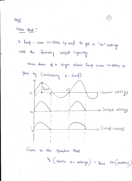
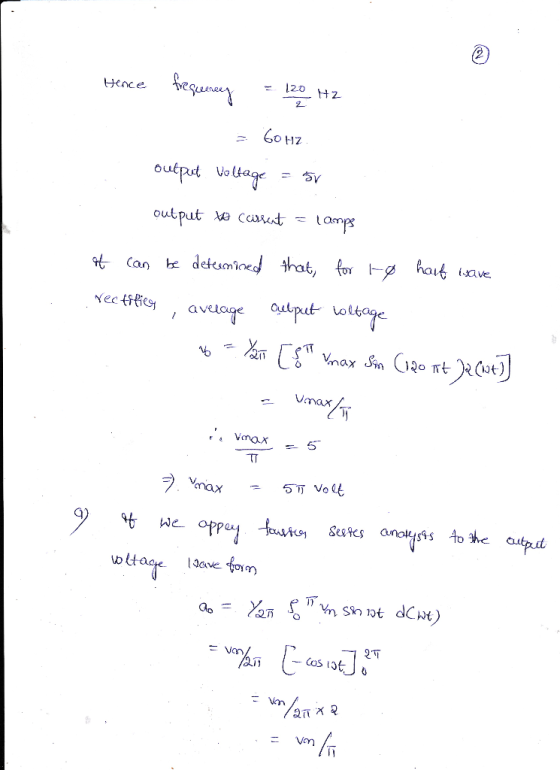
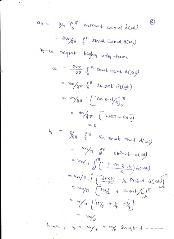
Please use smoothing capacitor and include simulation verification the following output capacity: A half-wave rectifier is used to get a "de" voltage with Output voltage 5 VDc Output Curre...
For your choice of input voltage, load resistor and the value of the ripple voltage (as percent of Vdc) design a circuit for the half-wave rectifier. Assuming the value of Van for the diode, calc...
 For your choice of input voltage, load resistor and the value of the ripple voltage (as percent of Vdc) design a circuit for the half-wave rectifier. Assuming the value of Van for the diode, calculate theoretically all parameters of the rectifier: Vp, Vdc, Idc, C, Isc, PIV and diode conducting interval. Simulate the designed circuit first without the capacitor filter and show on the graphs of the input, output and diode voltages and load and diode currents. Show on the...
QUESTION 5 (15 points) a. You have a power supply which is a full-wave rectifier with a capacitor filter It operates fr...
 QUESTION 5 (15 points) a. You have a power supply which is a full-wave rectifier with a capacitor filter It operates from the mains and provides an output of Voc-: 20 V with 20% ripple, when the load current is 2 A. Calculate the maximum and minimum values of the output waveform of this power supply. b. Now you will design a series voltage regulator between the power supply described in part (a) and an electronic device operating at 12...
D *4.80 It is required to use a peak rectifier to design a de power supply...
 D *4.80 It is required to use a peak rectifier to design a de power supply that provides an average de output voltage of 12 V on which a maximum of ±1-V ripple is allowed. The rectifier feeds a load of 200 2. The rectifier is fed from the line voltage (120 V rms, 60 Hz) through a transformer. The diodes available have 0.7-V drop when conducting. If the designer opts for the half-wave circuit: (a) Specify the rms voltage...
QUESTION 5 (15 points) a. You have a power supply which is a full-wave rectifier with a capacitor filter. It operates f...
 QUESTION 5 (15 points) a. You have a power supply which is a full-wave rectifier with a capacitor filter. It operates from the mains and provides an output of Voc-20 V with 20% ripple, when the load current is 2 A Calculate the maximum and minimum values of the output waveform of this power supply. b. Now you will design a series voltage regulator between the power supply described in part (a) and an electronic device operating at 12 VDC...
please help i do not understand lyue 2 The controlled half-wave rectifier of Figure 3 has...
 please help i do not understand
lyue 2 The controlled half-wave rectifier of Figure 3 has an ac input of 120 V rms at 60 Hz, R=20 0, L= 200 mH, and Vdc =80 V. The delay angle a is 30 degrees. Determine (a) an expression for the current, (b) the power absorbed by the resistor and (c) the power absorbed by the de source in the load, R W-0001 th 1.sin(01) Vs Figure 3
please help i do not understand
lyue 2 The controlled half-wave rectifier of Figure 3 has an ac input of 120 V rms at 60 Hz, R=20 0, L= 200 mH, and Vdc =80 V. The delay angle a is 30 degrees. Determine (a) an expression for the current, (b) the power absorbed by the resistor and (c) the power absorbed by the de source in the load, R W-0001 th 1.sin(01) Vs Figure 3
Design a FULL WAVE BRIDGE RECTIFIER circuit that will: Take 120volts ac, 60 hz, sinusoidal waveform...
 Design a FULL WAVE BRIDGE RECTIFIER circuit that will:
Take 120volts ac, 60 hz, sinusoidal waveform and convert
it to a “regulated “dc value
giving 12 volts +, - 1 volt across a 2000-ohm output
load resistor with no more than 2%
ripple voltage.
You may assume:
a. An ideal power transformer as discussed in class.
b. For hand computations, you must assume a diode given by
Figure 4.8 page 185.
c. A filter capacitor sized per the textbook equation...
Design a FULL WAVE BRIDGE RECTIFIER circuit that will:
Take 120volts ac, 60 hz, sinusoidal waveform and convert
it to a “regulated “dc value
giving 12 volts +, - 1 volt across a 2000-ohm output
load resistor with no more than 2%
ripple voltage.
You may assume:
a. An ideal power transformer as discussed in class.
b. For hand computations, you must assume a diode given by
Figure 4.8 page 185.
c. A filter capacitor sized per the textbook equation...
1. The following half-wave rectifier circuit has a 120-Vrms source at 60-Hz, R-500-2, and C-100-uF. Determine:...
 1. The following half-wave rectifier circuit has a 120-Vrms source at 60-Hz, R-500-2, and C-100-uF. Determine: a) An expression for the output voltage. b) The peak-to-peak voltage variation on the output. c) An expression for capacitor current. d) The peak diode current. e) Confirm your answers through OrCAD solution. Display all graphs and tabulate the results ID IR le Vs Vm Sin(wt) R. T100 Vo soon
Problem 3 (40 points): A single-phase half-wave rectifier shown in the following figure has a pure...
 Problem 3 (40 points): A single-phase half-wave rectifier shown in the following figure has a pure resistive load of RL112. Assume Vm 311V, f- 60Hz. (1) Determine the efficiency, the FF, the RF, the TUF, the PIV of the diode, the CF of the input currernt and the input PF (2) Design a C-filter so that the ripple factor of the output voltage is less than 5%; (3) With the value of capacitor C determined from (2), calculate the average...
Use matlab to solve Project A half-wave diode rectifier shown in the following Fig. 1 is...
 Use matlab to solve
Project A half-wave diode rectifier shown in the following Fig. 1 is an electrical cirouit that coeverts AC voltage to DC voltage. The voltage of the source is y,Sin(utwhere -f in whicfis the frequency. The operation of the circuit is illustrated in Fig. 2 where the dashod line shows the source veltage and the solid line shows the voltage across the resistor Diode Time Fig. 1 In the first cycle, thediode is on (conductingcurrent)fromに0umi 4Atthstme thediodetums...
Use matlab to solve
Project A half-wave diode rectifier shown in the following Fig. 1 is an electrical cirouit that coeverts AC voltage to DC voltage. The voltage of the source is y,Sin(utwhere -f in whicfis the frequency. The operation of the circuit is illustrated in Fig. 2 where the dashod line shows the source veltage and the solid line shows the voltage across the resistor Diode Time Fig. 1 In the first cycle, thediode is on (conductingcurrent)fromに0umi 4Atthstme thediodetums...
Need help with 5-9 please 1. Connect four diodes for proper use of full wave rectifier....
 Need help with 5-9 please
1. Connect four diodes for proper use of full wave rectifier. Show Connection for 60Hz, 20 Vrms AC input. 2. Determine waveshape of rectified output. Determine PIV on the diodes. 3. Find the peak to peak output ripple if filter capacitor C=200uf, and Ro-50002 4. Determine Vpc. Can we use Vz=20v, Izk=5mA Zener regulator, explain? 5. Determine series resistor Rs for proper regulation if Pz=5W and show the Circuit 6. Determine, IL max 7. For...
Need help with 5-9 please
1. Connect four diodes for proper use of full wave rectifier. Show Connection for 60Hz, 20 Vrms AC input. 2. Determine waveshape of rectified output. Determine PIV on the diodes. 3. Find the peak to peak output ripple if filter capacitor C=200uf, and Ro-50002 4. Determine Vpc. Can we use Vz=20v, Izk=5mA Zener regulator, explain? 5. Determine series resistor Rs for proper regulation if Pz=5W and show the Circuit 6. Determine, IL max 7. For...
 For your choice of input voltage, load resistor and the value of the ripple voltage (as percent of Vdc) design a circuit for the half-wave rectifier. Assuming the value of Van for the diode, calculate theoretically all parameters of the rectifier: Vp, Vdc, Idc, C, Isc, PIV and diode conducting interval. Simulate the designed circuit first without the capacitor filter and show on the graphs of the input, output and diode voltages and load and diode currents. Show on the...
 QUESTION 5 (15 points) a. You have a power supply which is a full-wave rectifier with a capacitor filter It operates from the mains and provides an output of Voc-: 20 V with 20% ripple, when the load current is 2 A. Calculate the maximum and minimum values of the output waveform of this power supply. b. Now you will design a series voltage regulator between the power supply described in part (a) and an electronic device operating at 12...
 D *4.80 It is required to use a peak rectifier to design a de power supply that provides an average de output voltage of 12 V on which a maximum of ±1-V ripple is allowed. The rectifier feeds a load of 200 2. The rectifier is fed from the line voltage (120 V rms, 60 Hz) through a transformer. The diodes available have 0.7-V drop when conducting. If the designer opts for the half-wave circuit: (a) Specify the rms voltage...
 QUESTION 5 (15 points) a. You have a power supply which is a full-wave rectifier with a capacitor filter. It operates from the mains and provides an output of Voc-20 V with 20% ripple, when the load current is 2 A Calculate the maximum and minimum values of the output waveform of this power supply. b. Now you will design a series voltage regulator between the power supply described in part (a) and an electronic device operating at 12 VDC...
 please help i do not understand
lyue 2 The controlled half-wave rectifier of Figure 3 has an ac input of 120 V rms at 60 Hz, R=20 0, L= 200 mH, and Vdc =80 V. The delay angle a is 30 degrees. Determine (a) an expression for the current, (b) the power absorbed by the resistor and (c) the power absorbed by the de source in the load, R W-0001 th 1.sin(01) Vs Figure 3
please help i do not understand
lyue 2 The controlled half-wave rectifier of Figure 3 has an ac input of 120 V rms at 60 Hz, R=20 0, L= 200 mH, and Vdc =80 V. The delay angle a is 30 degrees. Determine (a) an expression for the current, (b) the power absorbed by the resistor and (c) the power absorbed by the de source in the load, R W-0001 th 1.sin(01) Vs Figure 3
 Design a FULL WAVE BRIDGE RECTIFIER circuit that will:
Take 120volts ac, 60 hz, sinusoidal waveform and convert
it to a “regulated “dc value
giving 12 volts +, - 1 volt across a 2000-ohm output
load resistor with no more than 2%
ripple voltage.
You may assume:
a. An ideal power transformer as discussed in class.
b. For hand computations, you must assume a diode given by
Figure 4.8 page 185.
c. A filter capacitor sized per the textbook equation...
Design a FULL WAVE BRIDGE RECTIFIER circuit that will:
Take 120volts ac, 60 hz, sinusoidal waveform and convert
it to a “regulated “dc value
giving 12 volts +, - 1 volt across a 2000-ohm output
load resistor with no more than 2%
ripple voltage.
You may assume:
a. An ideal power transformer as discussed in class.
b. For hand computations, you must assume a diode given by
Figure 4.8 page 185.
c. A filter capacitor sized per the textbook equation...
 1. The following half-wave rectifier circuit has a 120-Vrms source at 60-Hz, R-500-2, and C-100-uF. Determine: a) An expression for the output voltage. b) The peak-to-peak voltage variation on the output. c) An expression for capacitor current. d) The peak diode current. e) Confirm your answers through OrCAD solution. Display all graphs and tabulate the results ID IR le Vs Vm Sin(wt) R. T100 Vo soon
 Problem 3 (40 points): A single-phase half-wave rectifier shown in the following figure has a pure resistive load of RL112. Assume Vm 311V, f- 60Hz. (1) Determine the efficiency, the FF, the RF, the TUF, the PIV of the diode, the CF of the input currernt and the input PF (2) Design a C-filter so that the ripple factor of the output voltage is less than 5%; (3) With the value of capacitor C determined from (2), calculate the average...
 Use matlab to solve
Project A half-wave diode rectifier shown in the following Fig. 1 is an electrical cirouit that coeverts AC voltage to DC voltage. The voltage of the source is y,Sin(utwhere -f in whicfis the frequency. The operation of the circuit is illustrated in Fig. 2 where the dashod line shows the source veltage and the solid line shows the voltage across the resistor Diode Time Fig. 1 In the first cycle, thediode is on (conductingcurrent)fromに0umi 4Atthstme thediodetums...
Use matlab to solve
Project A half-wave diode rectifier shown in the following Fig. 1 is an electrical cirouit that coeverts AC voltage to DC voltage. The voltage of the source is y,Sin(utwhere -f in whicfis the frequency. The operation of the circuit is illustrated in Fig. 2 where the dashod line shows the source veltage and the solid line shows the voltage across the resistor Diode Time Fig. 1 In the first cycle, thediode is on (conductingcurrent)fromに0umi 4Atthstme thediodetums...
 Need help with 5-9 please
1. Connect four diodes for proper use of full wave rectifier. Show Connection for 60Hz, 20 Vrms AC input. 2. Determine waveshape of rectified output. Determine PIV on the diodes. 3. Find the peak to peak output ripple if filter capacitor C=200uf, and Ro-50002 4. Determine Vpc. Can we use Vz=20v, Izk=5mA Zener regulator, explain? 5. Determine series resistor Rs for proper regulation if Pz=5W and show the Circuit 6. Determine, IL max 7. For...
Need help with 5-9 please
1. Connect four diodes for proper use of full wave rectifier. Show Connection for 60Hz, 20 Vrms AC input. 2. Determine waveshape of rectified output. Determine PIV on the diodes. 3. Find the peak to peak output ripple if filter capacitor C=200uf, and Ro-50002 4. Determine Vpc. Can we use Vz=20v, Izk=5mA Zener regulator, explain? 5. Determine series resistor Rs for proper regulation if Pz=5W and show the Circuit 6. Determine, IL max 7. For...
Most questions answered within 3 hours.
-
In 2005, Derrek Lee led the National Baseball League with a
0.335 batting average, meaning that...
asked 6 minutes ago -
Write a recursive function moreFactors(a,b,fact) that does the
following:
1. Takes as an input 3 positive...
asked 5 minutes ago -
In order for corporations to behave ethically, they must,
ultimately, give up the profit motive.
...
asked 6 minutes ago -
Blue Spruce Corp. owns equipment that cost $63,400 when
purchased on January 1, 2017. It has...
asked 26 minutes ago -
A lottery exists where balls numbered 1 to 17 are placed in an
urn. To win,...
asked 1 hour ago -
Please explain steps:
An 80 kg swimmer steps off a platform 10 m above the water...
asked 1 hour ago -
26) Briefly describe, using words or simple diagrams, the
chemiosmotic theory for coupling oxidation to phosphorylation...
asked 3 hours ago -
Suppose that XX is a random variable with mean 16 and standard
deviation 5 . Also...
asked 4 hours ago -
Calculate the number density of argon gas at a temperature of
24C and a pressure of...
asked 7 hours ago -
Alternative
Classification
How to Estimate
Probabilities from Data? ( For continuous Attributes)
And How to generate...
asked 7 hours ago -
An explosion breaks a 20.0-kg object into three parts. The
object is initially moving at a...
asked 8 hours ago -
Calculate the approximate number of residues of Rubisco, which
is involved in carbon fixation in plants,...
asked 9 hours ago