Please use moment of distribution
Structural analysis
Homework Answers


Add Answer to:
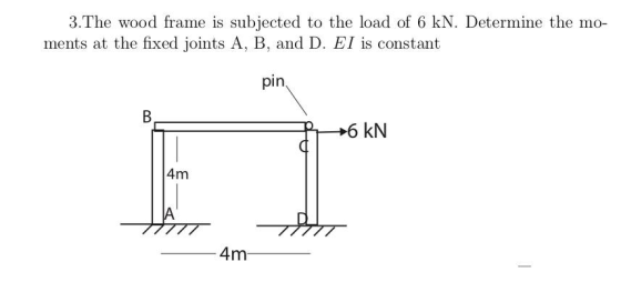
Please use moment of distribution Structural analysis 3.The wood frame is subjected to the load of 6 kN. Determine the mo ments at the fixed joints A, B, and D. EI is constant pin 4m 4m 3.The...
Part B) For the frame (no sidesway) below, determine the reactions and draw the shear and moment ...
 Part B) For the frame (no sidesway) below, determine the reactions and draw the shear and moment diagrams using the moment-distribution method of analysis. Joints A, B and E are fixed and all members are rigidly connected at C and D. You may perform the moment distribution by hand. E is constant, but I is as shown on the frame 50 kN 50 kN 4 m 6 kN/m 21 1.51 1.51 6 m 8 Part 3) Reanalyze the frame of...
2) (10 marks) a) The frame is subjected to the load of 4 kN which acts on member ABD at D. Determine the require...
 2) (10 marks) a) The frame is subjected to the load of 4 kN which acts on member ABD at D. Determine the required diameter of the pins at D and C if the allowable shear stress for the material is tallow 40 MPa. Pins C is subjected to double shear, whereas pin D is subjected to single shear. b) Determine the preferred basic size for the pins at D and C. 3) (10 marks) A sign is subjected to...
5-Use moment area method. Determine the vertical displacement of point D. Use moment area method. A is fixed, B is a hinge and C is a roller. Note that El is not constant. 2KN 2 KN/m EI EI D 2E...
 5-Use moment area method. Determine the vertical displacement of point D. Use moment area method. A is fixed, B is a hinge and C is a roller. Note that El is not constant. 2KN 2 KN/m EI EI D 2EI 1m
5-Use moment area method. Determine the vertical displacement of point D. Use moment area method. A is fixed, B is a hinge and C is a roller. Note that El is not constant. 2KN 2 KN/m EI EI D...
5-Use moment area method. Determine the vertical displacement of point D. Use moment area method. A is fixed, B is a hinge and C is a roller. Note that El is not constant. 2KN 2 KN/m EI EI D 2EI 1m
5-Use moment area method. Determine the vertical displacement of point D. Use moment area method. A is fixed, B is a hinge and C is a roller. Note that El is not constant. 2KN 2 KN/m EI EI D...
use moment Distribution approach 11-25. Determine the moments at joints B and C, thern draw the moment diagram for e...
 use moment Distribution approach
11-25. Determine the moments at joints B and C, thern draw the moment diagram for each member of the frame. The supports at A and D are pinned. EI is constant. 8 k 10 ft
use moment Distribution approach
11-25. Determine the moments at joints B and C, thern draw the moment diagram for each member of the frame. The supports at A and D are pinned. EI is constant. 8 k 10 ft
Please use moment-distribution method Problem 2. Solve the moments at all joints and supports of the...
 Please use moment-distribution method
Problem 2. Solve the moments at all joints and supports of the given frame using moment-distribution method. Assume the supports at A, C, and E are pins. El is constant. 12 kN/m 10 KN D 4 m 16 kN/m 15 kN B 3 m 4 m
Please use moment-distribution method
Problem 2. Solve the moments at all joints and supports of the given frame using moment-distribution method. Assume the supports at A, C, and E are pins. El is constant. 12 kN/m 10 KN D 4 m 16 kN/m 15 kN B 3 m 4 m
Moment distribution method Determine the moments at A, C, and D, then draw the moment diagram for each member of the...
 Moment distribution method
Determine the moments at A, C, and D, then draw the moment diagram for each member of the frame. Support A and joints C and D are fixed connected. El is constant Prob. 11-18 6 kN/m 6 m 8 m rn 7 m
Moment distribution method
Determine the moments at A, C, and D, then draw the moment diagram for each member of the frame. Support A and joints C and D are fixed connected. El is constant Prob. 11-18 6 kN/m 6 m 8 m rn 7 m
Question 2: Stiffness Method in Structural Analysis. Calculate the moment at the fixed end support for...
 Question 2: Stiffness Method in Structural Analysis. Calculate the moment at the fixed end support for the 2 span continuous beam structure as shown in Figure Q2 below using stiffness method. (Hint: Use superposition of fixed end and nodal load structure.) The continuous beam is fixed end supported at joint A. It is roller supported at joint B and C A point load of 80 kN is acting on member AB, 6 m from joint A. A uniform load of...
Determine the displacement at C. Assume A is a fixed support, B is a pin, and D is a roller. EI is constant. Use the conjugate beam method.
 Determine the displacement at C. Assume A is a fixed support, B is a pin, and D is a roller. EI is
constant. Use the conjugate beam method.
Determine the displacement at C. Assume A is a fixed support, B is a pin, and D is a roller. EI is
constant. Use the conjugate beam method.
Use moment distribution method or slope deflection method. The frame shown if Fig. 2.1 is supporting...
 Use moment distribution method or slope deflection
method.
The frame shown if Fig. 2.1 is supporting a lateral load of 60 kN and a gravity load of 50 kNIm. Neglect the weight of the members (a) Determine th reaction forces. (b) Draw the axial, shear, and bending moment and qualitative deflected shape diagrams of the frame. Specify values at a change of loading positions and at all points of zero shear and moment. Use slope-deflection method 2m Fig. 2.1 w...
Use moment distribution method or slope deflection
method.
The frame shown if Fig. 2.1 is supporting a lateral load of 60 kN and a gravity load of 50 kNIm. Neglect the weight of the members (a) Determine th reaction forces. (b) Draw the axial, shear, and bending moment and qualitative deflected shape diagrams of the frame. Specify values at a change of loading positions and at all points of zero shear and moment. Use slope-deflection method 2m Fig. 2.1 w...
Use the Moment Distribution Method to analyse the frame when subjected to the loading shown. Dimensions and load values...
 Use the Moment Distribution Method to analyse the frame when subjected to the loading shown. Dimensions and load values, which depend on your student ID, are given in the table below Determine the member forces and support reactions required in the table below Enter your answers in the space provided. Dimensions 5.4 m 2.6 m 6.8 m 3.4 m 280 kN lied actions 285 kN 13 kN/m Provide Answer for the followings to an accuracy of 2.5% sult required Absol...
 Part B) For the frame (no sidesway) below, determine the reactions and draw the shear and moment diagrams using the moment-distribution method of analysis. Joints A, B and E are fixed and all members are rigidly connected at C and D. You may perform the moment distribution by hand. E is constant, but I is as shown on the frame 50 kN 50 kN 4 m 6 kN/m 21 1.51 1.51 6 m 8 Part 3) Reanalyze the frame of...
 2) (10 marks) a) The frame is subjected to the load of 4 kN which acts on member ABD at D. Determine the required diameter of the pins at D and C if the allowable shear stress for the material is tallow 40 MPa. Pins C is subjected to double shear, whereas pin D is subjected to single shear. b) Determine the preferred basic size for the pins at D and C. 3) (10 marks) A sign is subjected to...
 5-Use moment area method. Determine the vertical displacement of point D. Use moment area method. A is fixed, B is a hinge and C is a roller. Note that El is not constant. 2KN 2 KN/m EI EI D 2EI 1m
5-Use moment area method. Determine the vertical displacement of point D. Use moment area method. A is fixed, B is a hinge and C is a roller. Note that El is not constant. 2KN 2 KN/m EI EI D...
5-Use moment area method. Determine the vertical displacement of point D. Use moment area method. A is fixed, B is a hinge and C is a roller. Note that El is not constant. 2KN 2 KN/m EI EI D 2EI 1m
5-Use moment area method. Determine the vertical displacement of point D. Use moment area method. A is fixed, B is a hinge and C is a roller. Note that El is not constant. 2KN 2 KN/m EI EI D...
 use moment Distribution approach
11-25. Determine the moments at joints B and C, thern draw the moment diagram for each member of the frame. The supports at A and D are pinned. EI is constant. 8 k 10 ft
use moment Distribution approach
11-25. Determine the moments at joints B and C, thern draw the moment diagram for each member of the frame. The supports at A and D are pinned. EI is constant. 8 k 10 ft
 Please use moment-distribution method
Problem 2. Solve the moments at all joints and supports of the given frame using moment-distribution method. Assume the supports at A, C, and E are pins. El is constant. 12 kN/m 10 KN D 4 m 16 kN/m 15 kN B 3 m 4 m
Please use moment-distribution method
Problem 2. Solve the moments at all joints and supports of the given frame using moment-distribution method. Assume the supports at A, C, and E are pins. El is constant. 12 kN/m 10 KN D 4 m 16 kN/m 15 kN B 3 m 4 m
 Moment distribution method
Determine the moments at A, C, and D, then draw the moment diagram for each member of the frame. Support A and joints C and D are fixed connected. El is constant Prob. 11-18 6 kN/m 6 m 8 m rn 7 m
Moment distribution method
Determine the moments at A, C, and D, then draw the moment diagram for each member of the frame. Support A and joints C and D are fixed connected. El is constant Prob. 11-18 6 kN/m 6 m 8 m rn 7 m
 Question 2: Stiffness Method in Structural Analysis. Calculate the moment at the fixed end support for the 2 span continuous beam structure as shown in Figure Q2 below using stiffness method. (Hint: Use superposition of fixed end and nodal load structure.) The continuous beam is fixed end supported at joint A. It is roller supported at joint B and C A point load of 80 kN is acting on member AB, 6 m from joint A. A uniform load of...
 Use moment distribution method or slope deflection
method.
The frame shown if Fig. 2.1 is supporting a lateral load of 60 kN and a gravity load of 50 kNIm. Neglect the weight of the members (a) Determine th reaction forces. (b) Draw the axial, shear, and bending moment and qualitative deflected shape diagrams of the frame. Specify values at a change of loading positions and at all points of zero shear and moment. Use slope-deflection method 2m Fig. 2.1 w...
Use moment distribution method or slope deflection
method.
The frame shown if Fig. 2.1 is supporting a lateral load of 60 kN and a gravity load of 50 kNIm. Neglect the weight of the members (a) Determine th reaction forces. (b) Draw the axial, shear, and bending moment and qualitative deflected shape diagrams of the frame. Specify values at a change of loading positions and at all points of zero shear and moment. Use slope-deflection method 2m Fig. 2.1 w...
 Use the Moment Distribution Method to analyse the frame when subjected to the loading shown. Dimensions and load values, which depend on your student ID, are given in the table below Determine the member forces and support reactions required in the table below Enter your answers in the space provided. Dimensions 5.4 m 2.6 m 6.8 m 3.4 m 280 kN lied actions 285 kN 13 kN/m Provide Answer for the followings to an accuracy of 2.5% sult required Absol...
Most questions answered within 3 hours.
-
Calculate the number density of argon gas at a temperature of
24C and a pressure of...
asked 2 hours ago -
Alternative
Classification
How to Estimate
Probabilities from Data? ( For continuous Attributes)
And How to generate...
asked 2 hours ago -
An explosion breaks a 20.0-kg object into three parts. The
object is initially moving at a...
asked 3 hours ago -
Calculate the approximate number of residues of Rubisco, which
is involved in carbon fixation in plants,...
asked 4 hours ago -
Other decisions about scientific claims can have a much broader
impact.ENERGYarrow-10x10.png, environment, health, security - all...
asked 5 hours ago -
I need to write a research paper and work cited about this
topic: The United States...
asked 6 hours ago -
Hello! I was wondering if I could have some help?
If the vapor pressure of carvone...
asked 6 hours ago -
An economist wants to estimate the mean per capita income (in
thousands of dollars) for a...
asked 6 hours ago -
What would be the input/output characteristic of a circuit
obtained by putting two of your 2's-complementers...
asked 6 hours ago -
In Drosophila, the transition from the syncytial blastoderm
stage to the cellular blastoderm stage is a...
asked 7 hours ago -
Project management question:
Name 3 different types of resources (hint: humans are one
type)
asked 7 hours ago -
Consider the following reaction: C 2H 2( g) + 2H 2( g) C 2H 6(
g)...
asked 7 hours ago