 Reinforced Concrete Design
Homework Answers

Add Answer to:
Reinforced Concrete Design Please answer it with good write . Problem 1: The reinforced concrete cantilever beam shown is subjected to a concentrated load P- 2 kips, at its free end. Determine th...
A rectangular reinforced concrete beam of span 16 ft supports a concentrated load of 40 kips...
 A rectangular reinforced concrete beam of span 16 ft supports a concentrated load of 40 kips at mid-point of the beam and a uniformly-distributed load of 4 kips/ft over the entire span. Given: (a) The breadth of the beam is 18 inches. (b) Concrete compressive strength, fc, is 3500 psi. (c) Rebar is Grade 40 steel i) Determine the maximum moment and maximum shear acting on the beam. ii) Determine the minimum effective depth 'd' of the beam section (rounded...
A rectangular reinforced concrete beam of span 16 ft supports a concentrated load of 40 kips...
A rectangular reinforced concrete beam of span 16 ft supports a concentrated load of 40 kips at mid-point of the beam and a uniformly-distributed load of 4 kips/ft over the entire span. Given: (a) The breadth of the beam is 18 inches. (b) Concrete compressive strength, f 'c, is 3500 psi. (c) Rebar is Grade 40 steel i) Determine the maximum moment and maximum shear acting on the beam. ii) Determine the minimum effective depth 'd' of the beam section...
The cantilever beam is subjected to a concentrated load of P = 29 kips. The cross-sectional dimen...
 The cantilever beam is subjected to a concentrated load of
P = 29 kips. The cross-sectional dimensions of the
wide-flange shape are shown in the second figure. Assume
yH=3.4 in., yK=1.6 in.,
d=10.6 in., tw=0.323 in.,
tf=0.507 in., bf=6.12 in.
Determine:
The cantilever beam is subjected to a concentrated load of P 29 kips. The cross-sectional dimensions of the wide-flange shape are shown in the second figure. Assume y,-3.4 in., Ук_ 1.6 in., d-10.6 in., t,-0.323 in., tf-0.507 in., bf-6.12...
The cantilever beam is subjected to a concentrated load of
P = 29 kips. The cross-sectional dimensions of the
wide-flange shape are shown in the second figure. Assume
yH=3.4 in., yK=1.6 in.,
d=10.6 in., tw=0.323 in.,
tf=0.507 in., bf=6.12 in.
Determine:
The cantilever beam is subjected to a concentrated load of P 29 kips. The cross-sectional dimensions of the wide-flange shape are shown in the second figure. Assume y,-3.4 in., Ук_ 1.6 in., d-10.6 in., t,-0.323 in., tf-0.507 in., bf-6.12...
The cantilever beam is subjected to a concentrated load of P = 52 kips. The cross-sectional...
 The cantilever beam is
subjected to a concentrated load of P = 52 kips. The
cross-sectional dimensions of the wide-flange shape are shown in
the second figure. Assume yH = 3.2 in.,
yK = 1.8 in., d = 10.8 in.,
tw = 0.354 in., tf = 0.414
in., bf = 6.62 in. Determine:
(a) the shear stress τH at point H, which is located 3.2
in. below the centroid of the wide-flange shape.
(b) the maximum horizontal shear stress τmax...
The cantilever beam is
subjected to a concentrated load of P = 52 kips. The
cross-sectional dimensions of the wide-flange shape are shown in
the second figure. Assume yH = 3.2 in.,
yK = 1.8 in., d = 10.8 in.,
tw = 0.354 in., tf = 0.414
in., bf = 6.62 in. Determine:
(a) the shear stress τH at point H, which is located 3.2
in. below the centroid of the wide-flange shape.
(b) the maximum horizontal shear stress τmax...
The cantilever beam is subjected to a concentrated load of P = 35 kips. The cross-sectional...
 The cantilever beam is subjected to a concentrated load of P = 35 kips. The cross-sectional dimensions of the wide-flange shape are shown in the second figure. Assume yH = 4.6 in., ?? 1.8 in, d = 14.6 in., tw= 0.307 in., tf= 0.331 in., br= 7.55 in. Determine: (a) the shear stress tH at point H, which is located 4.6 in. below the centroid of the wide-flange shape. (b) the maximum horizontal shear stress Tmax in the wide-flange shape...
Problem 1 (50% 16.0 The normal weight reinforced concrete beam shown has a 15' cantilever span...
 Problem 1 (50% 16.0 The normal weight reinforced concrete beam shown has a 15' cantilever span and the following properties fc 3000 psi fy - 40 ksi 18.0 6-10 bars (a) (10%) Determine the cracking moment of the beam. 24.0 Do not complete any code checks (min/max steel, min. beam width, etc.) 3.0
no need to draw sketch The short cantilever below carries a heavy concentrated load near the...
 no need to draw sketch
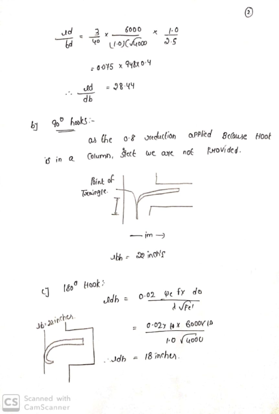
The short cantilever below carries a heavy concentrated load near the end of the beam. Three number 8 bars are used in tension and you can assume they are adequately anchored in the supporting column. There is at least 2 in. cover from the end of the bars to the end of the beams. Detemine if hooks are needed to fully develop the number 8 bars. If they are needed, calculate the development length of...
no need to draw sketch
The short cantilever below carries a heavy concentrated load near the end of the beam. Three number 8 bars are used in tension and you can assume they are adequately anchored in the supporting column. There is at least 2 in. cover from the end of the bars to the end of the beams. Detemine if hooks are needed to fully develop the number 8 bars. If they are needed, calculate the development length of...
HELP! Problem 6 Development Length (30 pts.) The required reinforcement steel area "As" for the lightweight reinforced concrete beam of figure 3 is 2.88 si. The No. 8 top bars are uncoated. C...
 HELP!
Problem 6 Development Length (30 pts.) The required reinforcement steel area "As" for the lightweight reinforced concrete beam of figure 3 is 2.88 si. The No. 8 top bars are uncoated. Compute the development length (d), İffy 60,000 psi and fc 3.500 psi. a) Use the simplified equation Table 8-1) b) Use the ACI Equation 25.4.2.3a (Equation 8-10) c) Use the ACI Equation 25.4.2.3a with Ktr 0 (Equation 8-10) 18 3" 3@4 123 3" 448 bars 3.14 in2 26...
HELP!
Problem 6 Development Length (30 pts.) The required reinforcement steel area "As" for the lightweight reinforced concrete beam of figure 3 is 2.88 si. The No. 8 top bars are uncoated. Compute the development length (d), İffy 60,000 psi and fc 3.500 psi. a) Use the simplified equation Table 8-1) b) Use the ACI Equation 25.4.2.3a (Equation 8-10) c) Use the ACI Equation 25.4.2.3a with Ktr 0 (Equation 8-10) 18 3" 3@4 123 3" 448 bars 3.14 in2 26...
Problem 2 (25 points) A rectangular reinforced concrete beam has a width b-15 inches and effecti...
 Problem 2 (25 points) A rectangular reinforced concrete beam has a width b-15 inches and effecti Concrete com ve depth d-24 inches. orcement fy- 60 ksi. imate load - 6 k/R pressive strength fe -4,000 psi and yield stress of steel reinf The beam is simply supported and subjected to a uniformly distributed ulti that includes the weight of the beam. Span is 28 feet. Assume interior exposure. s and show the proposed shear reinforcement Design the beam for shear...
Problem 1 Reinforced Concrete T-Flanged Sections (50 pts.) You are required to analyze and design...
 Problem 1 Reinforced Concrete T-Flanged Sections (50 pts.) You are required to analyze and design the propped cantilever t-section from HM 4 but for shear only. Draw shear V and moment M diagrams for uniformly distributed load throughout the 30ft span and equally concentrated loads at 10ft and 30ft. Recall that the connection at the left joint N1 is fixed. The connection at 20ft N3 is a roller. The right end node N2 is a free end. Use a concrete...
 A rectangular reinforced concrete beam of span 16 ft supports a concentrated load of 40 kips at mid-point of the beam and a uniformly-distributed load of 4 kips/ft over the entire span. Given: (a) The breadth of the beam is 18 inches. (b) Concrete compressive strength, fc, is 3500 psi. (c) Rebar is Grade 40 steel i) Determine the maximum moment and maximum shear acting on the beam. ii) Determine the minimum effective depth 'd' of the beam section (rounded...
 The cantilever beam is subjected to a concentrated load of
P = 29 kips. The cross-sectional dimensions of the
wide-flange shape are shown in the second figure. Assume
yH=3.4 in., yK=1.6 in.,
d=10.6 in., tw=0.323 in.,
tf=0.507 in., bf=6.12 in.
Determine:
The cantilever beam is subjected to a concentrated load of P 29 kips. The cross-sectional dimensions of the wide-flange shape are shown in the second figure. Assume y,-3.4 in., Ук_ 1.6 in., d-10.6 in., t,-0.323 in., tf-0.507 in., bf-6.12...
The cantilever beam is subjected to a concentrated load of
P = 29 kips. The cross-sectional dimensions of the
wide-flange shape are shown in the second figure. Assume
yH=3.4 in., yK=1.6 in.,
d=10.6 in., tw=0.323 in.,
tf=0.507 in., bf=6.12 in.
Determine:
The cantilever beam is subjected to a concentrated load of P 29 kips. The cross-sectional dimensions of the wide-flange shape are shown in the second figure. Assume y,-3.4 in., Ук_ 1.6 in., d-10.6 in., t,-0.323 in., tf-0.507 in., bf-6.12...
 The cantilever beam is
subjected to a concentrated load of P = 52 kips. The
cross-sectional dimensions of the wide-flange shape are shown in
the second figure. Assume yH = 3.2 in.,
yK = 1.8 in., d = 10.8 in.,
tw = 0.354 in., tf = 0.414
in., bf = 6.62 in. Determine:
(a) the shear stress τH at point H, which is located 3.2
in. below the centroid of the wide-flange shape.
(b) the maximum horizontal shear stress τmax...
The cantilever beam is
subjected to a concentrated load of P = 52 kips. The
cross-sectional dimensions of the wide-flange shape are shown in
the second figure. Assume yH = 3.2 in.,
yK = 1.8 in., d = 10.8 in.,
tw = 0.354 in., tf = 0.414
in., bf = 6.62 in. Determine:
(a) the shear stress τH at point H, which is located 3.2
in. below the centroid of the wide-flange shape.
(b) the maximum horizontal shear stress τmax...
 The cantilever beam is subjected to a concentrated load of P = 35 kips. The cross-sectional dimensions of the wide-flange shape are shown in the second figure. Assume yH = 4.6 in., ?? 1.8 in, d = 14.6 in., tw= 0.307 in., tf= 0.331 in., br= 7.55 in. Determine: (a) the shear stress tH at point H, which is located 4.6 in. below the centroid of the wide-flange shape. (b) the maximum horizontal shear stress Tmax in the wide-flange shape...
 Problem 1 (50% 16.0 The normal weight reinforced concrete beam shown has a 15' cantilever span and the following properties fc 3000 psi fy - 40 ksi 18.0 6-10 bars (a) (10%) Determine the cracking moment of the beam. 24.0 Do not complete any code checks (min/max steel, min. beam width, etc.) 3.0
 no need to draw sketch
The short cantilever below carries a heavy concentrated load near the end of the beam. Three number 8 bars are used in tension and you can assume they are adequately anchored in the supporting column. There is at least 2 in. cover from the end of the bars to the end of the beams. Detemine if hooks are needed to fully develop the number 8 bars. If they are needed, calculate the development length of...
no need to draw sketch
The short cantilever below carries a heavy concentrated load near the end of the beam. Three number 8 bars are used in tension and you can assume they are adequately anchored in the supporting column. There is at least 2 in. cover from the end of the bars to the end of the beams. Detemine if hooks are needed to fully develop the number 8 bars. If they are needed, calculate the development length of...
 HELP!
Problem 6 Development Length (30 pts.) The required reinforcement steel area "As" for the lightweight reinforced concrete beam of figure 3 is 2.88 si. The No. 8 top bars are uncoated. Compute the development length (d), İffy 60,000 psi and fc 3.500 psi. a) Use the simplified equation Table 8-1) b) Use the ACI Equation 25.4.2.3a (Equation 8-10) c) Use the ACI Equation 25.4.2.3a with Ktr 0 (Equation 8-10) 18 3" 3@4 123 3" 448 bars 3.14 in2 26...
HELP!
Problem 6 Development Length (30 pts.) The required reinforcement steel area "As" for the lightweight reinforced concrete beam of figure 3 is 2.88 si. The No. 8 top bars are uncoated. Compute the development length (d), İffy 60,000 psi and fc 3.500 psi. a) Use the simplified equation Table 8-1) b) Use the ACI Equation 25.4.2.3a (Equation 8-10) c) Use the ACI Equation 25.4.2.3a with Ktr 0 (Equation 8-10) 18 3" 3@4 123 3" 448 bars 3.14 in2 26...
 Problem 2 (25 points) A rectangular reinforced concrete beam has a width b-15 inches and effecti Concrete com ve depth d-24 inches. orcement fy- 60 ksi. imate load - 6 k/R pressive strength fe -4,000 psi and yield stress of steel reinf The beam is simply supported and subjected to a uniformly distributed ulti that includes the weight of the beam. Span is 28 feet. Assume interior exposure. s and show the proposed shear reinforcement Design the beam for shear...
 Problem 1 Reinforced Concrete T-Flanged Sections (50 pts.) You are required to analyze and design the propped cantilever t-section from HM 4 but for shear only. Draw shear V and moment M diagrams for uniformly distributed load throughout the 30ft span and equally concentrated loads at 10ft and 30ft. Recall that the connection at the left joint N1 is fixed. The connection at 20ft N3 is a roller. The right end node N2 is a free end. Use a concrete...
Most questions answered within 3 hours.
-
If you’re standing at the bottom of a hill and asked to evaluate
it while being...
asked 32 minutes ago -
1. Which region has taken the lead in the world of
e-waste handling?
a) European Union...
asked 26 minutes ago -
A 8.15- g bullet from a 9-mm pistol has a velocity of 366.0 m/s.
It strikes...
asked 1 hour ago -
The outstanding bonds of Alpha Extracts have a yield to maturity
of 7.4 percent and a...
asked 1 hour ago -
The Problem: The Case of the Harmonizing Vacations
Your CEO is exploring partnering with a European...
asked 3 hours ago -
A chemical equation is balanced by adding coefficients in front
of some formulas so that the...
asked 3 hours ago -
From the literature (reference your sources): What are the
lattice parameters of calcite and aragonite? Why...
asked 3 hours ago -
Your system is rejecting the question am asking which is
preceded by a case study. It...
asked 4 hours ago -
3. On January 2, 2000, Larry creates a trust with himself as
trustee. Larry as trustee...
asked 4 hours ago -
A member of the volleyball team spikes the ball. During this
process, she changes the velocity...
asked 4 hours ago -
Are adult gamers less likely to use a gaming console (Xbox,
PlayStation, Wii, etc...) than teen...
asked 5 hours ago -
The University of
Texas recently reported that 43% of college students aged 18-24
would spend their...
asked 5 hours ago