
Homework Answers


Add Answer to:
Question 1 (60 points) Consider the following block diagram where G (s) Froarss RMs) GIs) Gls) (a) Sketch the root locus assuming a proportional controller is used. (b) Assume design spocifications r...
Question 1 (60 points) Consider the following block diagram where G(s)- Controller R(s) G(s) (a) Sketch the root locus assuming a proportional controller is used. [25 points] (b) Design specifica...
 Question 1 (60 points) Consider the following block diagram where G(s)- Controller R(s) G(s) (a) Sketch the root locus assuming a proportional controller is used. [25 points] (b) Design specifications require a closed-loop pole at (-3+j1). Design a lead compensator to make sure the root locus goes through this point. For the design, pick the pole of the compensator at-23 and analytically find its zero. (Hint: Lead compensator transfer function will be Ge (s)$+23 First plot the poles and zeros...
1 (60 points) the following block diagram where G(o)-3 (+1+30s+s) Gri (a) Sketch the root locus...
 1 (60 points) the following block diagram where G(o)-3 (+1+30s+s) Gri (a) Sketch the root locus assuming a proportional controller is uned (b) Assume design specifications require a closed-loop pole at (-2+/1), Design a to make sure the root locus goes through this point. Afher the design, determine the value of K that will create the closed-loop pole at the desired poin
3. Consider the tilt control block diagram shown below R(s) DesiredG(s) 12 s(s+10)(s+70) Y(s) Til...
 3. Consider the tilt control block diagram shown below R(s) DesiredG(s) 12 s(s+10)(s+70) Y(s) Tilt tilt Design specifications require an overshoot of less than 5% and a settling time of less than 0.6 seconds. (a) Use MATLAB to sketch the root locus (rlocus command) with a proportional controller and use the root locus to determine a value for K (if any) that will satisfy the design requirements (b) Design a lead compensator Ge(s) to satisfy the design specifications. You can...
Q. 1 (5 marks) For the system in Fig. (a). Assume proportion control, Gc(s)-K, sketch the root lo...
 pls answer dont just copy other solution or ur catching a
dislike
Q. 1 (5 marks) For the system in Fig. (a). Assume proportion control, Gc(s)-K, sketch the root locus for the closed-loop system (b). Using the angle condition, prove that s12 +j2 is not on the root locus. (c). Design a lead compensator Ge(s) - K such that the dominant closed-loop poles are located at s1--2 2. (d), What are the zero and pole of lead compensator G() (e)....
pls answer dont just copy other solution or ur catching a
dislike
Q. 1 (5 marks) For the system in Fig. (a). Assume proportion control, Gc(s)-K, sketch the root locus for the closed-loop system (b). Using the angle condition, prove that s12 +j2 is not on the root locus. (c). Design a lead compensator Ge(s) - K such that the dominant closed-loop poles are located at s1--2 2. (d), What are the zero and pole of lead compensator G() (e)....
yUCni ias the block diagram shown below. Controller Process Sensor (a) (5%) Sketch the root locus of the closed-loop system. (b) (5%) Determine the range of K that the closed-loop system is stabl...
 yUCni ias the block diagram shown below. Controller Process Sensor (a) (5%) Sketch the root locus of the closed-loop system. (b) (5%) Determine the range of K that the closed-loop system is stable. (c) (5%) Find the percentage of overshoot and the steady state error due to a unit step input of the open loop system process. (d) (5%) Find the steady-state error due to a unit step input of the closed-loop syste as a function of the design parameter...
A system having an open loop transfer function of G(S) = K10/(S+2)(3+1) has a root locus...
 A system having an open loop transfer function of G(S) = K10/(S+2)(3+1) has a root locus plot as shown below. The location of the roots for a system gain of K= 0.248 is show on the plot. At this location the system has a damping factor of 0.708 and a settling time of 4/1.5 = 2.67 seconds. A lead compensator is to be used to improve the transient response. (Note that nothing is plotted on the graph except for that...
Problem 3 (25%): The closed-loop system has the block diagram shown below. Controlle Process Sensor s + l (a) (5%) Sketch the root locus of the closed-loop system. (b) (5%) Determine the range of...
 Problem 3 (25%): The closed-loop system has the block diagram shown below. Controlle Process Sensor s + l (a) (5%) Sketch the root locus of the closed-loop system. (b) (5%) Determine the range of K that the closed-loop system is stable. (c) (5%) Find the percentage of overshoot and the steady state error due to a unit step input of the open loop system process. (d) (5%) Find the steady-state error due to a unit step input of the closed-loop...
2. Controller Design For each of the following plants G, design a compensator G, so that the closed loop system KG, G (1 + KG, G has two dominant poles near 2 ± i Plot a root locus plot for the s...
 2. Controller Design For each of the following plants G, design a compensator G, so that the closed loop system KG, G (1 + KG, G has two dominant poles near 2 ± i Plot a root locus plot for the system before adding the compensator and another plot for after. Use the simplest G that you can find. Determine the gain K that will achieve the desired poles 142
2. Controller Design For each of the following plants G,...
2. Controller Design For each of the following plants G, design a compensator G, so that the closed loop system KG, G (1 + KG, G has two dominant poles near 2 ± i Plot a root locus plot for the system before adding the compensator and another plot for after. Use the simplest G that you can find. Determine the gain K that will achieve the desired poles 142
2. Controller Design For each of the following plants G,...
Given a transfer function: a. Sketch the root locus of G(s) b. Calculate the proportional gain required for to place the dominant poles at this point: s = -1.5-j3.5 c for G(s) give the controller :...
 Given a transfer function:
a. Sketch the root locus of G(s)
b. Calculate the proportional gain required for to place the
dominant poles at this point: s = -1.5-j3.5
c for G(s) give the controller :
considered closed loop, plot root locus for this system
7 (s + 5) (s + 2)(s2 + 6s + 10) G (s) H(s) = Ks +5
7 (s + 5) (s + 2)(s2 + 6s + 10) G (s)
H(s) = Ks +5
Given a transfer function:
a. Sketch the root locus of G(s)
b. Calculate the proportional gain required for to place the
dominant poles at this point: s = -1.5-j3.5
c for G(s) give the controller :
considered closed loop, plot root locus for this system
7 (s + 5) (s + 2)(s2 + 6s + 10) G (s) H(s) = Ks +5
7 (s + 5) (s + 2)(s2 + 6s + 10) G (s)
H(s) = Ks +5
Question 5 The root locus of a system is provided in the following figure. C(s) R(s) + (s-2%s -I)...
 Question 5 The root locus of a system is provided in the following figure. C(s) R(s) + (s-2%s -I) 2.00 1.50 1.00 . 50 -.50 -2.00 2.00 -2.00 1.00 1.00 Real (a) Find the location of closed-loop system poles (design poles) to provide S -0.707 (use the provided scaled graph to avoid numerical calculations). (b) Find the value of K corresponding to the design poles. (c) Find the value of settling time corresponding to the design poles. (d) It is...
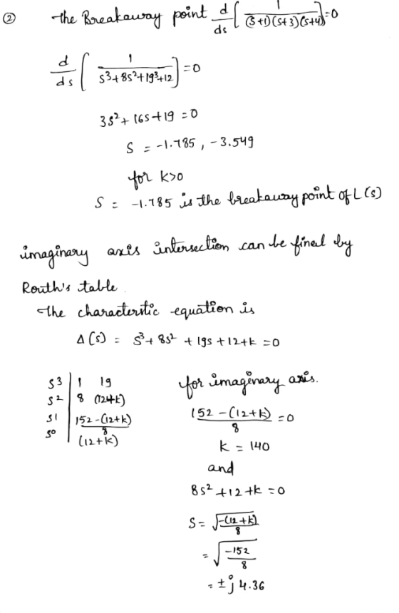
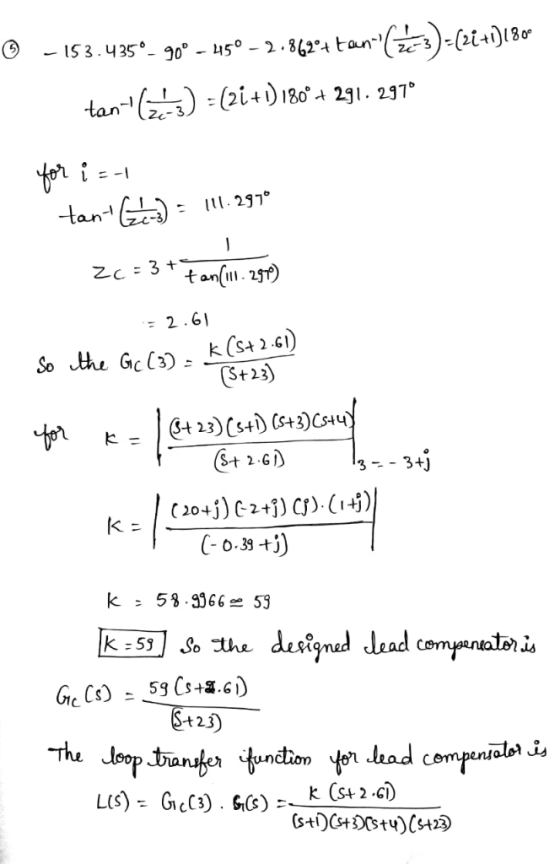
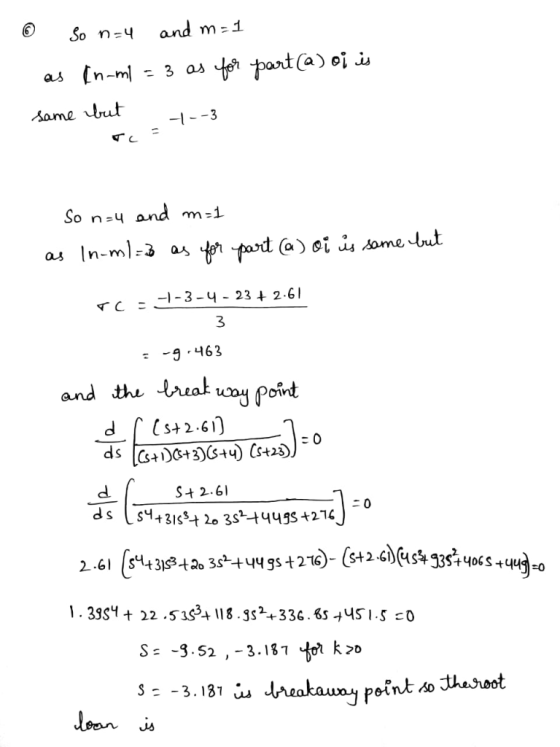
 Question 1 (60 points) Consider the following block diagram where G(s)- Controller R(s) G(s) (a) Sketch the root locus assuming a proportional controller is used. [25 points] (b) Design specifications require a closed-loop pole at (-3+j1). Design a lead compensator to make sure the root locus goes through this point. For the design, pick the pole of the compensator at-23 and analytically find its zero. (Hint: Lead compensator transfer function will be Ge (s)$+23 First plot the poles and zeros...
 1 (60 points) the following block diagram where G(o)-3 (+1+30s+s) Gri (a) Sketch the root locus assuming a proportional controller is uned (b) Assume design specifications require a closed-loop pole at (-2+/1), Design a to make sure the root locus goes through this point. Afher the design, determine the value of K that will create the closed-loop pole at the desired poin
 3. Consider the tilt control block diagram shown below R(s) DesiredG(s) 12 s(s+10)(s+70) Y(s) Tilt tilt Design specifications require an overshoot of less than 5% and a settling time of less than 0.6 seconds. (a) Use MATLAB to sketch the root locus (rlocus command) with a proportional controller and use the root locus to determine a value for K (if any) that will satisfy the design requirements (b) Design a lead compensator Ge(s) to satisfy the design specifications. You can...
 pls answer dont just copy other solution or ur catching a
dislike
Q. 1 (5 marks) For the system in Fig. (a). Assume proportion control, Gc(s)-K, sketch the root locus for the closed-loop system (b). Using the angle condition, prove that s12 +j2 is not on the root locus. (c). Design a lead compensator Ge(s) - K such that the dominant closed-loop poles are located at s1--2 2. (d), What are the zero and pole of lead compensator G() (e)....
pls answer dont just copy other solution or ur catching a
dislike
Q. 1 (5 marks) For the system in Fig. (a). Assume proportion control, Gc(s)-K, sketch the root locus for the closed-loop system (b). Using the angle condition, prove that s12 +j2 is not on the root locus. (c). Design a lead compensator Ge(s) - K such that the dominant closed-loop poles are located at s1--2 2. (d), What are the zero and pole of lead compensator G() (e)....
 yUCni ias the block diagram shown below. Controller Process Sensor (a) (5%) Sketch the root locus of the closed-loop system. (b) (5%) Determine the range of K that the closed-loop system is stable. (c) (5%) Find the percentage of overshoot and the steady state error due to a unit step input of the open loop system process. (d) (5%) Find the steady-state error due to a unit step input of the closed-loop syste as a function of the design parameter...
 A system having an open loop transfer function of G(S) = K10/(S+2)(3+1) has a root locus plot as shown below. The location of the roots for a system gain of K= 0.248 is show on the plot. At this location the system has a damping factor of 0.708 and a settling time of 4/1.5 = 2.67 seconds. A lead compensator is to be used to improve the transient response. (Note that nothing is plotted on the graph except for that...
 Problem 3 (25%): The closed-loop system has the block diagram shown below. Controlle Process Sensor s + l (a) (5%) Sketch the root locus of the closed-loop system. (b) (5%) Determine the range of K that the closed-loop system is stable. (c) (5%) Find the percentage of overshoot and the steady state error due to a unit step input of the open loop system process. (d) (5%) Find the steady-state error due to a unit step input of the closed-loop...
 2. Controller Design For each of the following plants G, design a compensator G, so that the closed loop system KG, G (1 + KG, G has two dominant poles near 2 ± i Plot a root locus plot for the system before adding the compensator and another plot for after. Use the simplest G that you can find. Determine the gain K that will achieve the desired poles 142
2. Controller Design For each of the following plants G,...
2. Controller Design For each of the following plants G, design a compensator G, so that the closed loop system KG, G (1 + KG, G has two dominant poles near 2 ± i Plot a root locus plot for the system before adding the compensator and another plot for after. Use the simplest G that you can find. Determine the gain K that will achieve the desired poles 142
2. Controller Design For each of the following plants G,...
 Given a transfer function:
a. Sketch the root locus of G(s)
b. Calculate the proportional gain required for to place the
dominant poles at this point: s = -1.5-j3.5
c for G(s) give the controller :
considered closed loop, plot root locus for this system
7 (s + 5) (s + 2)(s2 + 6s + 10) G (s) H(s) = Ks +5
7 (s + 5) (s + 2)(s2 + 6s + 10) G (s)
H(s) = Ks +5
Given a transfer function:
a. Sketch the root locus of G(s)
b. Calculate the proportional gain required for to place the
dominant poles at this point: s = -1.5-j3.5
c for G(s) give the controller :
considered closed loop, plot root locus for this system
7 (s + 5) (s + 2)(s2 + 6s + 10) G (s) H(s) = Ks +5
7 (s + 5) (s + 2)(s2 + 6s + 10) G (s)
H(s) = Ks +5
 Question 5 The root locus of a system is provided in the following figure. C(s) R(s) + (s-2%s -I) 2.00 1.50 1.00 . 50 -.50 -2.00 2.00 -2.00 1.00 1.00 Real (a) Find the location of closed-loop system poles (design poles) to provide S -0.707 (use the provided scaled graph to avoid numerical calculations). (b) Find the value of K corresponding to the design poles. (c) Find the value of settling time corresponding to the design poles. (d) It is...
Most questions answered within 3 hours.
-
Are there such things as microscopic multicellular animal
parasites? If so, please give examples.
asked 3 minutes ago -
Under common law, right of survivorship was automatically a
feature of which type of co-tenancy?
a....
asked 4 minutes ago -
Problem 03.019 Annual Worth Calculations
Find the value of x that makes the equivalent annual
worth...
asked 7 minutes ago -
At 1 bar, how much energy is required to heat 61.0 g of H2O(s)
at −12.0...
asked 24 minutes ago -
Find the mixed-strategy equilibrium to the Battle of the sexes
game in Figure 5.1 below
Hockey...
asked 26 minutes ago -
Use the following information to answer the next three
questions.
QUESTION 5
As of today, the...
asked 32 minutes ago -
Using the specific identification method: Date Units purchased
Cost per unit Ending inventory March 1 15...
asked 34 minutes ago -
PLEASE HELP, NO ONE IS ANSWERING MY QUESTION AND IT IS SUE TODAY
WORTH 20% OF...
asked 49 minutes ago -
α = 0.0007889 T, I = 2.9 A
Other Magnetic Fields: First, based on your
value...
asked 49 minutes ago -
This assignment is a continuation of the 2nd one. You as a HR
Manager, select an...
asked 51 minutes ago -
Hastings Entertainment has a beta of 0.64. If the market return
is expected to be 13.80...
asked 1 hour ago -
9. Depository institutions are always:
a. illiquid
b. profitable
c. insolvent
d. all of the above...
asked 1 hour ago