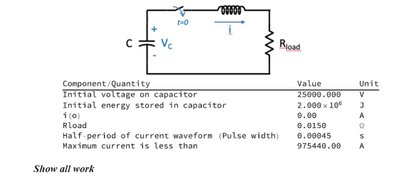
You have been asked to design a circuit, shown below, that will
deliver a high-current, slightly
underdamped, sinusoidal current pulse to a resistive load when the
switch is closed at t = 0. You
are given the design requirements and parameters listed in the
table:
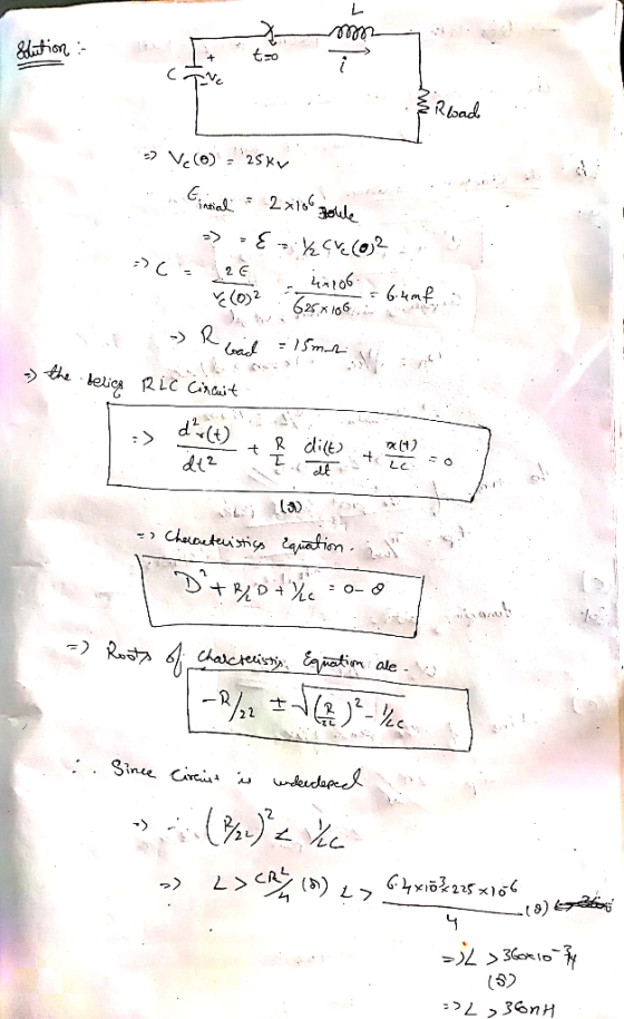
a) What values of L and C are required to meet the
specifications?
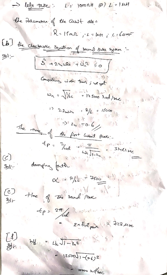
b) Calculate the time of the first current peak.
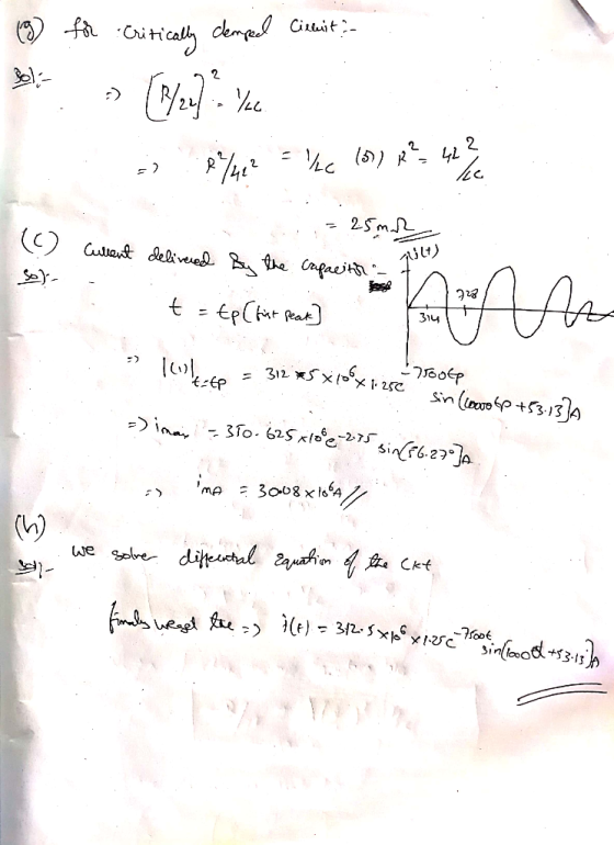
c) Calculate the maximum current delivered by the capacitor?
d) Calculate the value of the damping factor, (alpha), for this
circuit?
e) Calculate the time of the second peak of the current (negative
direction)?
f) What is the damped radian frequency, (omega)d, for this
circuit?
g) At what value of Rload will the circuit become critically
damped?
h) Sketch i(t), with labeled scales on both the time and amplitude
axes.
Homework Answers
Add Answer to:
You have been asked to design a circuit, shown below, that will deliver a high-current, slightly underdamped, sinusoidal current pulse to a resistive load when the switch is closed at t = 0. You are g...
In the circuit shown below, switch S has been closed for a very long time and it is opened at t = 0
 Q3. In the circuit shown below, switch S has been closed for a very long time and it is opened at t = 0. Find the solution for the current i(t) passing through the inductor. Q4. In the circuit shown, the initial capacitor voltage is v(0) =5 V. (a) Find the capacitor voltage v(r) for t > 0. (b) Find the current io(t).
To design a high efficiency d.c., to d.c power converter with the given specifications min 10V max 15V nominal (regulated) 8V Input voltage: Output voltage: Nominal load current: 4A Inductor current...
 To design a high efficiency d.c., to d.c power converter with the given specifications min 10V max 15V nominal (regulated) 8V Input voltage: Output voltage: Nominal load current: 4A Inductor current ripple: 0.1A max Switching frequency: 30 kHz Output voltage ripple: 20 mV Define a suitable power circuit topology to meet the above specification? Sketch a circuit diagram of the chosen power circuit topology (a) Define the minimum and maximum duty cycles assuming that the control circuit keeps the output...
The switch in the circuit shown has been closed for a long time and is opened at t = 0. Find
 The switch in the circuit shown has been closed for a long time and is opened at t = 0. Find a) The initial value of v(t), b) The time constant for t>0. c) The numerical expression for v(t) after the switch has been opened, d) The initial energy stored in the capacitor, and e) The length of time required to dissipate 75% of the initially stored energy.
nde) Figare 18 Circuit for Problem 15 Analysis 1. Plot the input and output vollage wavefoems nlt) and lt) as wel as the capacitor current iclt) for the input wavelorm shown in Fig ure 1....
 nde) Figare 18 Circuit for Problem 15 Analysis 1. Plot the input and output vollage wavefoems nlt) and lt) as wel as the capacitor current iclt) for the input wavelorm shown in Fig ure 1.10 on the next page, Assume the capacitoris initially discharged 2 Determine the following numerical descriptors for lf) and iclf (a) Voltage values of t) at times-250, 650, and 960ms. (b) Peak capacitor current t Discass the relationship between the plots of the capacitor current ic(t)...
Design a FULL WAVE BRIDGE RECTIFIER circuit that will: Take 120volts ac, 60 hz, sinusoidal waveform...
 Design a FULL WAVE BRIDGE RECTIFIER circuit that will:
Take 120volts ac, 60 hz, sinusoidal waveform and convert
it to a “regulated “dc value
giving 12 volts +, - 1 volt across a 2000-ohm output
load resistor with no more than 2%
ripple voltage.
You may assume:
a. An ideal power transformer as discussed in class.
b. For hand computations, you must assume a diode given by
Figure 4.8 page 185.
c. A filter capacitor sized per the textbook equation...
Design a FULL WAVE BRIDGE RECTIFIER circuit that will:
Take 120volts ac, 60 hz, sinusoidal waveform and convert
it to a “regulated “dc value
giving 12 volts +, - 1 volt across a 2000-ohm output
load resistor with no more than 2%
ripple voltage.
You may assume:
a. An ideal power transformer as discussed in class.
b. For hand computations, you must assume a diode given by
Figure 4.8 page 185.
c. A filter capacitor sized per the textbook equation...
do not use s domain method ,use only differential equation 3. In the circuit shown, switch 1 has been closed for a long time before it is opened at t 0, and switch 2 has been opened for a long time b...
 do not use s domain method ,use only differential equation
3. In the circuit shown, switch 1 has been closed for a long time before it is opened at t 0, and switch 2 has been opened for a long time before it is closed at t = 0. SW2 sw, 0.5Ω R2 1(2 A, 20 A i(t) 0.5 H a. Find the initial voltage v(O)- Vo across the capacitor and initial current through the inductor (0) lo at t...
do not use s domain method ,use only differential equation
3. In the circuit shown, switch 1 has been closed for a long time before it is opened at t 0, and switch 2 has been opened for a long time before it is closed at t = 0. SW2 sw, 0.5Ω R2 1(2 A, 20 A i(t) 0.5 H a. Find the initial voltage v(O)- Vo across the capacitor and initial current through the inductor (0) lo at t...
Engineering circuit analysis by Hayt 8th edition question 27 and figure 9.43 I think 10u(1-t) means 10 (for t<1)...
 Engineering circuit analysis by Hayt
8th edition
question 27 and figure 9.43
I think 10u(1-t) means 10 (for t<1) and 0
(for t>1)
then, I can't remove this current source because it
continuously make 10micro A
(at t=500ms, t=1.002ms)
I don't know what's wrong now..
366 26. For the circuit of Fig. 9,43, 1 30-) mA. (a) Select R, so th O)6 V (b) Compute e2 ms). (c) Determine the settling, time of t capacitor voltage. (d) Is the inductor...
Engineering circuit analysis by Hayt
8th edition
question 27 and figure 9.43
I think 10u(1-t) means 10 (for t<1) and 0
(for t>1)
then, I can't remove this current source because it
continuously make 10micro A
(at t=500ms, t=1.002ms)
I don't know what's wrong now..
366 26. For the circuit of Fig. 9,43, 1 30-) mA. (a) Select R, so th O)6 V (b) Compute e2 ms). (c) Determine the settling, time of t capacitor voltage. (d) Is the inductor...
MATLAB question. Please answer all the questions and also upload the code by MATLAB. Thanks. Down vote if no code provided. For the circuit shown above, at the moment t = 0, the switch is closed, fin...
 MATLAB question. Please answer all the questions and also upload
the code by MATLAB. Thanks. Down vote if no code provided.
For the circuit shown above, at the moment t = 0, the switch is closed, find w(t) for 120, No energy is stored in the capacitor and inductor at moment t-0 1. Write the dynamic model for RLC circuit after t> 0? a. Show all vour work and calculations b. Write down the characteristic equation of the transfer function...
MATLAB question. Please answer all the questions and also upload
the code by MATLAB. Thanks. Down vote if no code provided.
For the circuit shown above, at the moment t = 0, the switch is closed, find w(t) for 120, No energy is stored in the capacitor and inductor at moment t-0 1. Write the dynamic model for RLC circuit after t> 0? a. Show all vour work and calculations b. Write down the characteristic equation of the transfer function...
 To design a high efficiency d.c., to d.c power converter with the given specifications min 10V max 15V nominal (regulated) 8V Input voltage: Output voltage: Nominal load current: 4A Inductor current ripple: 0.1A max Switching frequency: 30 kHz Output voltage ripple: 20 mV Define a suitable power circuit topology to meet the above specification? Sketch a circuit diagram of the chosen power circuit topology (a) Define the minimum and maximum duty cycles assuming that the control circuit keeps the output...
 nde) Figare 18 Circuit for Problem 15 Analysis 1. Plot the input and output vollage wavefoems nlt) and lt) as wel as the capacitor current iclt) for the input wavelorm shown in Fig ure 1.10 on the next page, Assume the capacitoris initially discharged 2 Determine the following numerical descriptors for lf) and iclf (a) Voltage values of t) at times-250, 650, and 960ms. (b) Peak capacitor current t Discass the relationship between the plots of the capacitor current ic(t)...
 Design a FULL WAVE BRIDGE RECTIFIER circuit that will:
Take 120volts ac, 60 hz, sinusoidal waveform and convert
it to a “regulated “dc value
giving 12 volts +, - 1 volt across a 2000-ohm output
load resistor with no more than 2%
ripple voltage.
You may assume:
a. An ideal power transformer as discussed in class.
b. For hand computations, you must assume a diode given by
Figure 4.8 page 185.
c. A filter capacitor sized per the textbook equation...
Design a FULL WAVE BRIDGE RECTIFIER circuit that will:
Take 120volts ac, 60 hz, sinusoidal waveform and convert
it to a “regulated “dc value
giving 12 volts +, - 1 volt across a 2000-ohm output
load resistor with no more than 2%
ripple voltage.
You may assume:
a. An ideal power transformer as discussed in class.
b. For hand computations, you must assume a diode given by
Figure 4.8 page 185.
c. A filter capacitor sized per the textbook equation...
 do not use s domain method ,use only differential equation
3. In the circuit shown, switch 1 has been closed for a long time before it is opened at t 0, and switch 2 has been opened for a long time before it is closed at t = 0. SW2 sw, 0.5Ω R2 1(2 A, 20 A i(t) 0.5 H a. Find the initial voltage v(O)- Vo across the capacitor and initial current through the inductor (0) lo at t...
do not use s domain method ,use only differential equation
3. In the circuit shown, switch 1 has been closed for a long time before it is opened at t 0, and switch 2 has been opened for a long time before it is closed at t = 0. SW2 sw, 0.5Ω R2 1(2 A, 20 A i(t) 0.5 H a. Find the initial voltage v(O)- Vo across the capacitor and initial current through the inductor (0) lo at t...
 Engineering circuit analysis by Hayt
8th edition
question 27 and figure 9.43
I think 10u(1-t) means 10 (for t<1) and 0
(for t>1)
then, I can't remove this current source because it
continuously make 10micro A
(at t=500ms, t=1.002ms)
I don't know what's wrong now..
366 26. For the circuit of Fig. 9,43, 1 30-) mA. (a) Select R, so th O)6 V (b) Compute e2 ms). (c) Determine the settling, time of t capacitor voltage. (d) Is the inductor...
Engineering circuit analysis by Hayt
8th edition
question 27 and figure 9.43
I think 10u(1-t) means 10 (for t<1) and 0
(for t>1)
then, I can't remove this current source because it
continuously make 10micro A
(at t=500ms, t=1.002ms)
I don't know what's wrong now..
366 26. For the circuit of Fig. 9,43, 1 30-) mA. (a) Select R, so th O)6 V (b) Compute e2 ms). (c) Determine the settling, time of t capacitor voltage. (d) Is the inductor...
 MATLAB question. Please answer all the questions and also upload
the code by MATLAB. Thanks. Down vote if no code provided.
For the circuit shown above, at the moment t = 0, the switch is closed, find w(t) for 120, No energy is stored in the capacitor and inductor at moment t-0 1. Write the dynamic model for RLC circuit after t> 0? a. Show all vour work and calculations b. Write down the characteristic equation of the transfer function...
MATLAB question. Please answer all the questions and also upload
the code by MATLAB. Thanks. Down vote if no code provided.
For the circuit shown above, at the moment t = 0, the switch is closed, find w(t) for 120, No energy is stored in the capacitor and inductor at moment t-0 1. Write the dynamic model for RLC circuit after t> 0? a. Show all vour work and calculations b. Write down the characteristic equation of the transfer function...
Most questions answered within 3 hours.
-
Estimate the diffusion coefficient for methyl phenyl sulfide in
water at 25 degrees Celcius.
asked 16 minutes ago -
10.g of a certain metal absorb 40. cal of heat and the temperature
is abserved to...
asked 1 hour ago -
The time to complete a standardized exam is approximately normal
with a mean of 70 minutes...
asked 53 minutes ago -
Two thousand randomly selected adults were asked whether or not
they have ever shopped on the...
asked 1 hour ago -
How many milliliters of 0.0695 M Ca( OH)
2would be required to exactly neutralize 176 mL...
asked 1 hour ago -
A telephone survey uses a random digit dialing machine to call
subjects. The random digit dialing...
asked 2 hours ago -
How can having too little or too much of a certain
protein cause problems for an...
asked 3 hours ago -
Assume a muscle has a PCSA = 20 cm2 and Lo = 12 cm. Assume it...
asked 5 hours ago -
What is the yield to maturity of a ten-year, $1,000 bond with a
5.2% coupon rate...
asked 5 hours ago -
A mass m = 5 kg is tied on one end of a rope and is...
asked 6 hours ago -
The Average sales price of single-family houses in Charlotte is
$210,000 with a standard deviation of...
asked 6 hours ago -
Target Costing
Laser Impressions, Inc., manufactures color laser printers.
Model J20 presently sells for $225 and...
asked 6 hours ago