
Homework Answers
Add Answer to:
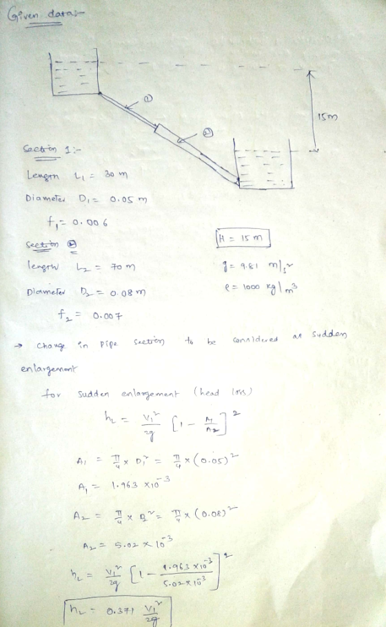
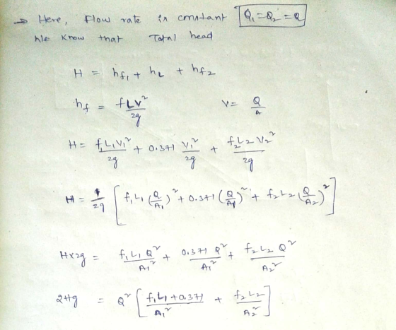
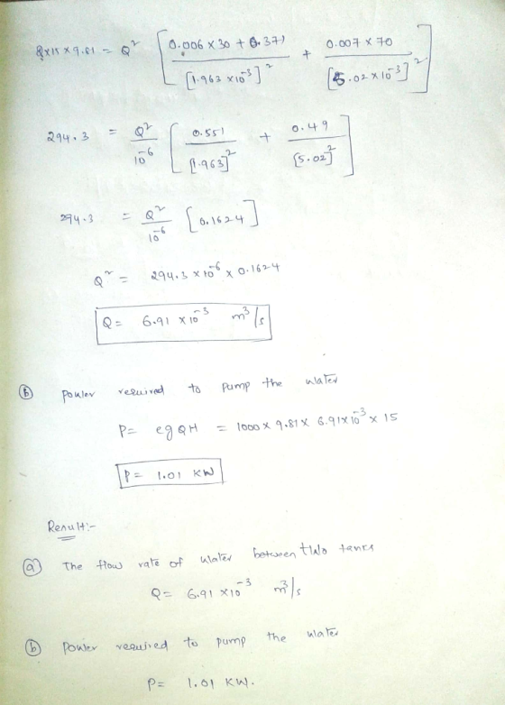
Question D.1 A2 Not sure Water flows between two tanks connected by a 100 m long pipe as shown in figure D1-1 below The tanks have a free surface height difference of 15 m and are both open to a...
Air flows in a 0.50 m diameter pipe at a rate of 15 m/s as shown in Figure 6 Q4 (a) The pipe diameter changes to 1....
 Air flows in a 0.50 m diameter pipe at a rate of 15 m/s as shown in Figure 6 Q4 (a) The pipe diameter changes to 1.0 m through a sudden expansion K, Note: For sudden expansion: Assess the pressure rise across this expansion. i. (9 marks) Explain how there can be a pressure rise across the expansion when i there is an energy loss (K, # 0) (2 marks) D2-1.0m Di-0.50 m Q= 15 m/s (1) (2) Figure 6:...
(b) Water flows under gravity between two reservoirs through a pipe of length 5000m. The diameter of the pipe is 0.2 m...
 (b) Water flows under gravity between two reservoirs through a pipe of length 5000m. The diameter of the pipe is 0.2 m and the roughness size is 0.04 mm. The water levels in the two reservoirs are maintained with a difference of 50 m. Determine the discharge through the pipe. Neglect all minor losses. Use the attached Moody diagram for estimation of friction factor. (10 marks) (c) In (b), now include entry loss at the upper reservoir with loss coefficient...
The flowrate between tank A and tank B shown in Figure Q2 is to be increased by adding a second pipe (indicated by the dotted lines) running from node C to tank B. Elevation of the free surface in ta...
 The flowrate between tank A and tank B shown in Figure Q2 is to be increased by adding a second pipe (indicated by the dotted lines) running from node C to tank B. Elevation of the free surface in tank A is 8 m above that in tank B. Neglect minor losses and assume that the friction factor for each pipe is 0.005. (a) Obtain the primary flow rate Q in the system before installation of the second pipe. (b)...
Question 1 The figure below shows a simple water pipe network. Relevant pipe properties are given...
 Question 1 The figure below shows a simple water pipe network. Relevant pipe properties are given in the figure and table below. The major losses of the pipes can be calculated by Darcy Weisbach equation. The friction factor () for all pipes is 0.015. Assuming that minor losses in the pipe network can be ignored and the pipe network is on a horizontal plane, determine the flow rates in all pipes using Hardy Cross method. Also, calculate the pressure head...
Notre Dame University Faculty of Engineering Mechanical Engineering Dep Water flows through cast iron pipes and between the two tanks shown in Figure P4. The free sharp edge entrance. Bd by a dis...
 Notre Dame University Faculty of Engineering Mechanical Engineering Dep Water flows through cast iron pipes and between the two tanks shown in Figure P4. The free sharp edge entrance. Bd by a distance of 8 m. The water leaves Tank 1 through a contains a regular 90 threaded elbow and two unknown a regular 90° threaded elbow and a fully Branch pipeline 1 contains a regular 90 valves (valve 1 and valve 2). Branch pipeline 2 contains open gate valve....
please clearly indicate answer(s) 1. As shown in the figure, using a 6-m-long, 100 mm diameter...
 please clearly indicate answer(s)
1. As shown in the figure, using a 6-m-long, 100 mm diameter pipe and assuming a friction factor f-0.02, investigate the likelhood of cavitation if h-4 m and h = 3m Water temperature is 25 degrees Centigrade, 5101325 KP kinematic viscosity =156 m2/sec, flow velocity = 4 m/sec, neglect minor losses using 2. At the deign flow rate read the pump characteristics if the 6 in impeller is used (power, efficiency, head) 3. If the angular...
please clearly indicate answer(s)
1. As shown in the figure, using a 6-m-long, 100 mm diameter pipe and assuming a friction factor f-0.02, investigate the likelhood of cavitation if h-4 m and h = 3m Water temperature is 25 degrees Centigrade, 5101325 KP kinematic viscosity =156 m2/sec, flow velocity = 4 m/sec, neglect minor losses using 2. At the deign flow rate read the pump characteristics if the 6 in impeller is used (power, efficiency, head) 3. If the angular...
 Air flows in a 0.50 m diameter pipe at a rate of 15 m/s as shown in Figure 6 Q4 (a) The pipe diameter changes to 1.0 m through a sudden expansion K, Note: For sudden expansion: Assess the pressure rise across this expansion. i. (9 marks) Explain how there can be a pressure rise across the expansion when i there is an energy loss (K, # 0) (2 marks) D2-1.0m Di-0.50 m Q= 15 m/s (1) (2) Figure 6:...
 (b) Water flows under gravity between two reservoirs through a pipe of length 5000m. The diameter of the pipe is 0.2 m and the roughness size is 0.04 mm. The water levels in the two reservoirs are maintained with a difference of 50 m. Determine the discharge through the pipe. Neglect all minor losses. Use the attached Moody diagram for estimation of friction factor. (10 marks) (c) In (b), now include entry loss at the upper reservoir with loss coefficient...
 The flowrate between tank A and tank B shown in Figure Q2 is to be increased by adding a second pipe (indicated by the dotted lines) running from node C to tank B. Elevation of the free surface in tank A is 8 m above that in tank B. Neglect minor losses and assume that the friction factor for each pipe is 0.005. (a) Obtain the primary flow rate Q in the system before installation of the second pipe. (b)...
 Question 1 The figure below shows a simple water pipe network. Relevant pipe properties are given in the figure and table below. The major losses of the pipes can be calculated by Darcy Weisbach equation. The friction factor () for all pipes is 0.015. Assuming that minor losses in the pipe network can be ignored and the pipe network is on a horizontal plane, determine the flow rates in all pipes using Hardy Cross method. Also, calculate the pressure head...
 Notre Dame University Faculty of Engineering Mechanical Engineering Dep Water flows through cast iron pipes and between the two tanks shown in Figure P4. The free sharp edge entrance. Bd by a distance of 8 m. The water leaves Tank 1 through a contains a regular 90 threaded elbow and two unknown a regular 90° threaded elbow and a fully Branch pipeline 1 contains a regular 90 valves (valve 1 and valve 2). Branch pipeline 2 contains open gate valve....
 Notre Dame University Faculty of Engineering Mechanical Engineering Dep Water flows through cast iron pipes and between the two tanks shown in Figure P4. The free sharp edge entrance. Bd by a distance of 8 m. The water leaves Tank 1 through a contains a regular 90 threaded elbow and two unknown a regular 90° threaded elbow and a fully Branch pipeline 1 contains a regular 90 valves (valve 1 and valve 2). Branch pipeline 2 contains open gate valve....
 Notre Dame University Faculty of Engineering Mechanical Engineering Dep Water flows through cast iron pipes and between the two tanks shown in Figure P4. The free sharp edge entrance. Bd by a distance of 8 m. The water leaves Tank 1 through a contains a regular 90 threaded elbow and two unknown a regular 90° threaded elbow and a fully Branch pipeline 1 contains a regular 90 valves (valve 1 and valve 2). Branch pipeline 2 contains open gate valve....
 please clearly indicate answer(s)
1. As shown in the figure, using a 6-m-long, 100 mm diameter pipe and assuming a friction factor f-0.02, investigate the likelhood of cavitation if h-4 m and h = 3m Water temperature is 25 degrees Centigrade, 5101325 KP kinematic viscosity =156 m2/sec, flow velocity = 4 m/sec, neglect minor losses using 2. At the deign flow rate read the pump characteristics if the 6 in impeller is used (power, efficiency, head) 3. If the angular...
please clearly indicate answer(s)
1. As shown in the figure, using a 6-m-long, 100 mm diameter pipe and assuming a friction factor f-0.02, investigate the likelhood of cavitation if h-4 m and h = 3m Water temperature is 25 degrees Centigrade, 5101325 KP kinematic viscosity =156 m2/sec, flow velocity = 4 m/sec, neglect minor losses using 2. At the deign flow rate read the pump characteristics if the 6 in impeller is used (power, efficiency, head) 3. If the angular...
Most questions answered within 3 hours.
-
What are the negative effects of abruptly stopping the use of
all fossil fuels? Give at...
asked 4 minutes ago -
Given that many conflict are the result of different parties having
different interests, is it possible...
asked 9 minutes ago -
A 750 g block can slide uniformly along the horizontal track
when a string attached to...
asked 12 minutes ago -
In 2017, Juan entered into a contract to write a book. The
publisher advanced Juan $50,000,...
asked 26 minutes ago -
Determine the number of kinds of protons in each molecule (w/
respect to NMR spectroscopy). Drawing...
asked 36 minutes ago -
A jeweler whose near point is 68 cm from his eye uses a
magnifying glass as...
asked 34 minutes ago -
A company wants to determine how many units of each of two
products, A and B,...
asked 38 minutes ago -
The blood pressure of a person changes throughout the day.
Suppose the systolic blood pressure of...
asked 47 minutes ago -
A chemistry student desired to study sulfur. Sulfur exhibited
the following characteristics with oxygen:
(a) It...
asked 42 minutes ago -
An Atwood machine is constructed of a solid-disk frictionless
pulley of mass m3 and radius R....
asked 44 minutes ago -
what are the advantages of lanthanum hexaboride over tungsten
filament for electron emission
what is the...
asked 46 minutes ago -
Question 5
Your uncle offers to sell you his vintage Rolls Royce. He
suggests a payment...
asked 51 minutes ago