
Homework Answers
Please refer the datasheet. of the IC. type "74195 datasheet" in google and read the document for better understanding of the IC.
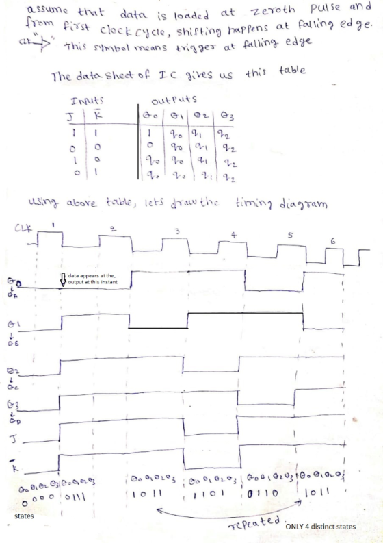
For drawing the above timing diagram, start at zeroth pulse and refer the table given above to determine the states of outputs at the falling edge of the clock. The IC is negative edge triggered and so the states change only at a falling edge of the clock.
Once the states change at the falling edge, they remain the same until next falling edge. The table provided above helps to find out how states will change at falling edge depending on J,K and Q0,Q1,Q2,Q3 values.
At any instant, J and K value equals value at Qc which is Q3 according to the datasheet. This is because J and K are connected to Qc
a)
for this 4 bit counter, there are only 4 distinct states and so it is a ring counter. If it was a johnson counter, we should have 8 states for 4 bit counter.
b)
It has 4 different states. For states, see the image attached.
Add Answer to:
17. The 74195 in Figure 17 is a synchronous load, 4-bit parallel-access shift register. For this exercise, the input data is loaded at the first active clock edge. (12 pts) 74195 DSTM2 SH/LD QB 1...
17. The 74195 in Figure 17 is a synchronous load, 4-bit parallel-access shift register. For this exercise, the input data is loaded at the first active clock edge. (12 pts) 74195 DSTM2 SH/LD 2 15...
 17. The 74195 in Figure 17 is a synchronous load, 4-bit parallel-access shift register. For this exercise, the input data is loaded at the first active clock edge. (12 pts) 74195 DSTM2 SH/LD 2 15 QC DSTMI 10 CLK CLR Figure 17 Use the circuit of Figure 17 to answer the following questions: a. Is this a ring counter or a Johnson counter? (2 pts) b. How many different states are available? (2 pts) Draw the timing diagram (four clock...
 17. The 74195 in Figure 17 is a synchronous load, 4-bit parallel-access shift register. For this exercise, the input data is loaded at the first active clock edge. (12 pts) 74195 DSTM2 SH/LD 2 15 QC DSTMI 10 CLK CLR Figure 17 Use the circuit of Figure 17 to answer the following questions: a. Is this a ring counter or a Johnson counter? (2 pts) b. How many different states are available? (2 pts) Draw the timing diagram (four clock...
Most questions answered within 3 hours.
-
New Air Heating and Cooling, manufactures furnaces and central
air units. The company pride itself on...
asked 6 minutes ago -
A coach uses a new technique to train gymnasts. Seven
gymnasts were randomly selected and their...
asked 2 hours ago -
While rotating the tires on your car you notice a rock [mass =
0.1 Kg] stuck...
asked 4 hours ago -
Using MARS simulator, write MIPS programs according to
the following scenarios: Receive a positive integer number...
asked 5 hours ago -
An object in front of a concave mirror has a real image that is
11.5 cm...
asked 6 hours ago -
Consider the reaction, C3 H8 + O2 --> CO2 + H2O. How many
moles of O2...
asked 7 hours ago -
You and your opponent both roll a fair die. If you both roll the
same number,...
asked 8 hours ago -
In a study of the accuracy of fast food drive-through orders,
Restaurant A had 257 accurate...
asked 8 hours ago -
Identify and describe in detail the four categories of
institutions that could be included in a...
asked 8 hours ago -
In python
class Customer:
def __init__(self, customer_id, last_name, first_name, phone_number, address):
self._customer_id = int(customer_id)
self._last_name =...
asked 8 hours ago -
What is an example of a limitation in implementing a new
ERP system and how it...
asked 8 hours ago -
In a section of 9.7cm of an artery with a radius of 2.6mm there
is a...
asked 8 hours ago