
Homework Answers


Add Answer to:
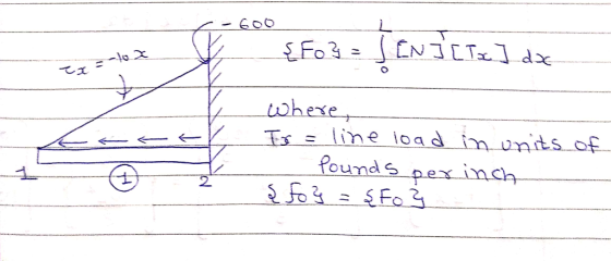
For the rod loaded axially as shown in the Figure, determine the axial displacement of the free end. Let E-30x 10s psi, A 2 in2, and L 60 in. Use the finite element stiffhess method. For...
Question 2 (10 points) For the rod loaded axially as shown in the Figure, determine the axial displacement of the free end. Let E-30 x 10 psi, A 2 in2, and L-60 in. Use the finite element stiffne...
 Question 2 (10 points) For the rod loaded axially as shown in the Figure, determine the axial displacement of the free end. Let E-30 x 10 psi, A 2 in2, and L-60 in. Use the finite element stiffness method.
Question 2 (10 points) For the rod loaded axially as shown in the Figure, determine the axial displacement of the free end. Let E-30 x 10 psi, A 2 in2, and L-60 in. Use the finite element stiffness method.
Question 2 (10 points) For the rod loaded axially as shown in the Figure, determine the axial displacement of the free end. Let E-30 x 10 psi, A 2 in2, and L-60 in. Use the finite element stiffness method.
Finite element problems For the bar elements shown in Figure P3–16, the global displacement have been...
 Finite element problems
For the bar elements shown in Figure P3–16, the global displacement have been deter- mined to be up = 0.5 in., V = 0.0, uy = 0.25 in., and V2 = 0.75 in. Determine the local x' displacements at each end of the bars. Let E = 12 x 106 psi, A = 0.5 in?, and L = 60 in. for each element. 45° 30° (a) (b) - Figure P3–16
Finite element problems
For the bar elements shown in Figure P3–16, the global displacement have been deter- mined to be up = 0.5 in., V = 0.0, uy = 0.25 in., and V2 = 0.75 in. Determine the local x' displacements at each end of the bars. Let E = 12 x 106 psi, A = 0.5 in?, and L = 60 in. for each element. 45° 30° (a) (b) - Figure P3–16
Please show all work for each step taken. Thank You. y loaded rod shown with area-2 in2, modulus E-10E6 psi, lengths: LAB-6 in and Lac- 12 lb and Fc 40 lb find the axial stress in sections AB and BC...
 Please show all work for each step taken. Thank You.
y loaded rod shown with area-2 in2, modulus E-10E6 psi, lengths: LAB-6 in and Lac- 12 lb and Fc 40 lb find the axial stress in sections AB and BC of the rod and the deflection at point C (2 points each).
y loaded rod shown with area-2 in2, modulus E-10E6 psi, lengths: LAB-6 in and Lac- 12 lb and Fc 40 lb find the axial stress in sections AB...
Please show all work for each step taken. Thank You.
y loaded rod shown with area-2 in2, modulus E-10E6 psi, lengths: LAB-6 in and Lac- 12 lb and Fc 40 lb find the axial stress in sections AB and BC of the rod and the deflection at point C (2 points each).
y loaded rod shown with area-2 in2, modulus E-10E6 psi, lengths: LAB-6 in and Lac- 12 lb and Fc 40 lb find the axial stress in sections AB...
Solve all problems using the finite element stiffness method. For the rigid frame shown in Figure P5-4, determine (1) the nodal displacements and rotation at node 4, (2) the reactions, and (3) the fo...
 Solve all problems using the finite element stiffness method. For the rigid frame shown in Figure P5-4, determine (1) the nodal displacements and rotation at node 4, (2) the reactions, and (3) the forces in each element. Then check equilibrium at node 4 Finally, draw the shear force and bending moment diagrams for each element. Let E 30x 103 ksi, A 8 in2, and I 800 in.4 for all elements. 20 kip 25 ft 25 ft 40 ft Figure P5-4...
Finite Element Method 5.17 Displacements of the three-member truss shown are confined to the plane of...
 Finite Element Method
5.17 Displacements of the three-member truss shown are confined to the plane of the figure, and points 1, 2 and 3 are fixed to the stationary rim. All members have the same A, E, and L a) Obtain the 2x2 stiffness matrix that operates on the horizontal and vertical degrees of freedom of the central node. b) Obtain the corresponding global force vector c) Solve for the displacements and for axial stress in member (2-4), when the...
Finite Element Method
5.17 Displacements of the three-member truss shown are confined to the plane of the figure, and points 1, 2 and 3 are fixed to the stationary rim. All members have the same A, E, and L a) Obtain the 2x2 stiffness matrix that operates on the horizontal and vertical degrees of freedom of the central node. b) Obtain the corresponding global force vector c) Solve for the displacements and for axial stress in member (2-4), when the...
For the bar subjected to axial load shown in Figure 1 to 2, determine the nodal...
 For the bar subjected to axial load shown in Figure 1 to 2, determine the nodal displacements and Reaction Force. Let Area = 2in^2, E= 30E6 psi = p(x) 300 lb/in 2 3 30 in 60 in x Figure 1 P(x) = 10x lb/in 2 3 30 in 60 in Figure 2.
Problèm GIVEN b 2) Three rod elements shown above are stress free when they are assembled...
 Problèm GIVEN b 2) Three rod elements shown above are stress free when they are assembled together and attached to the rigid walls A and D. Element (1) is steel with E1 30 x 103ksi, cross - sectional area Ai - 2.0 in, length L1-80 in and coefficient of thermal expansion α1=7x10⁻⁶/0F; the corresponding values for the aluminum element (2) are: E2 10 x 103ksi, A2-3.6 in, L,- 60 in, a2 13 x 10-6/oF; the corresponding values for the bronze...
Q2 (a) (0) Explain what is meant by interpolation in the Finite Element Method and why...
 Q2 (a) (0) Explain what is meant by interpolation in the Finite Element Method and why it is used (3 marks) What is a shape function? (3 marks) PLEASE TURN OVER 16363,16367 Page 2 of 3 0.2 (a) (Continued) (iii) For an isoparametric element, explain the relationship between shape functions, the geometry of the element and the shape the loaded element will deform to. (3 marks) (iv) Describe the relationship between structural equilibrium and the minimum potential energy state. (3...
QUESTION 4 (25 marks) A simply supported beam is loaded by an uniform distributed load, wkN/m, over the span of the beam, L, as shown in Figure Q4. (a) Determine the end reactions at point A and...
 QUESTION 4 (25 marks) A simply supported beam is loaded by an uniform distributed load, wkN/m, over the span of the beam, L, as shown in Figure Q4. (a) Determine the end reactions at point A and B in terms of w and L. (4 marks) (b) At an arbitrary point, x, express the internal mom (c) Show that the deflection curve of the beam under the loading situation is ent, M(x), in x, w, and L. (5 marks) 24EI...
structural analysis Figure Q() Question 2 For the bar assemblages shown in Figure Q(2), determine the nodal displacements, the forces in each element and the reactions. Use the direct stiffness me...
 structural analysis
Figure Q() Question 2 For the bar assemblages shown in Figure Q(2), determine the nodal displacements, the forces in each element and the reactions. Use the direct stiffness method (25 marks) 35 kN E-210 GPa 2 A4 x 10m2 1 m im
Figure Q() Question 2 For the bar assemblages shown in Figure Q(2), determine the nodal displacements, the forces in each element and the reactions. Use the direct stiffness method (25 marks) 35 kN E-210 GPa 2...
structural analysis
Figure Q() Question 2 For the bar assemblages shown in Figure Q(2), determine the nodal displacements, the forces in each element and the reactions. Use the direct stiffness method (25 marks) 35 kN E-210 GPa 2 A4 x 10m2 1 m im
Figure Q() Question 2 For the bar assemblages shown in Figure Q(2), determine the nodal displacements, the forces in each element and the reactions. Use the direct stiffness method (25 marks) 35 kN E-210 GPa 2...
 Question 2 (10 points) For the rod loaded axially as shown in the Figure, determine the axial displacement of the free end. Let E-30 x 10 psi, A 2 in2, and L-60 in. Use the finite element stiffness method.
Question 2 (10 points) For the rod loaded axially as shown in the Figure, determine the axial displacement of the free end. Let E-30 x 10 psi, A 2 in2, and L-60 in. Use the finite element stiffness method.
Question 2 (10 points) For the rod loaded axially as shown in the Figure, determine the axial displacement of the free end. Let E-30 x 10 psi, A 2 in2, and L-60 in. Use the finite element stiffness method.
 Finite element problems
For the bar elements shown in Figure P3–16, the global displacement have been deter- mined to be up = 0.5 in., V = 0.0, uy = 0.25 in., and V2 = 0.75 in. Determine the local x' displacements at each end of the bars. Let E = 12 x 106 psi, A = 0.5 in?, and L = 60 in. for each element. 45° 30° (a) (b) - Figure P3–16
Finite element problems
For the bar elements shown in Figure P3–16, the global displacement have been deter- mined to be up = 0.5 in., V = 0.0, uy = 0.25 in., and V2 = 0.75 in. Determine the local x' displacements at each end of the bars. Let E = 12 x 106 psi, A = 0.5 in?, and L = 60 in. for each element. 45° 30° (a) (b) - Figure P3–16
 Please show all work for each step taken. Thank You.
y loaded rod shown with area-2 in2, modulus E-10E6 psi, lengths: LAB-6 in and Lac- 12 lb and Fc 40 lb find the axial stress in sections AB and BC of the rod and the deflection at point C (2 points each).
y loaded rod shown with area-2 in2, modulus E-10E6 psi, lengths: LAB-6 in and Lac- 12 lb and Fc 40 lb find the axial stress in sections AB...
Please show all work for each step taken. Thank You.
y loaded rod shown with area-2 in2, modulus E-10E6 psi, lengths: LAB-6 in and Lac- 12 lb and Fc 40 lb find the axial stress in sections AB and BC of the rod and the deflection at point C (2 points each).
y loaded rod shown with area-2 in2, modulus E-10E6 psi, lengths: LAB-6 in and Lac- 12 lb and Fc 40 lb find the axial stress in sections AB...
 Solve all problems using the finite element stiffness method. For the rigid frame shown in Figure P5-4, determine (1) the nodal displacements and rotation at node 4, (2) the reactions, and (3) the forces in each element. Then check equilibrium at node 4 Finally, draw the shear force and bending moment diagrams for each element. Let E 30x 103 ksi, A 8 in2, and I 800 in.4 for all elements. 20 kip 25 ft 25 ft 40 ft Figure P5-4...
 Finite Element Method
5.17 Displacements of the three-member truss shown are confined to the plane of the figure, and points 1, 2 and 3 are fixed to the stationary rim. All members have the same A, E, and L a) Obtain the 2x2 stiffness matrix that operates on the horizontal and vertical degrees of freedom of the central node. b) Obtain the corresponding global force vector c) Solve for the displacements and for axial stress in member (2-4), when the...
Finite Element Method
5.17 Displacements of the three-member truss shown are confined to the plane of the figure, and points 1, 2 and 3 are fixed to the stationary rim. All members have the same A, E, and L a) Obtain the 2x2 stiffness matrix that operates on the horizontal and vertical degrees of freedom of the central node. b) Obtain the corresponding global force vector c) Solve for the displacements and for axial stress in member (2-4), when the...
 For the bar subjected to axial load shown in Figure 1 to 2, determine the nodal displacements and Reaction Force. Let Area = 2in^2, E= 30E6 psi = p(x) 300 lb/in 2 3 30 in 60 in x Figure 1 P(x) = 10x lb/in 2 3 30 in 60 in Figure 2.
 Problèm GIVEN b 2) Three rod elements shown above are stress free when they are assembled together and attached to the rigid walls A and D. Element (1) is steel with E1 30 x 103ksi, cross - sectional area Ai - 2.0 in, length L1-80 in and coefficient of thermal expansion α1=7x10⁻⁶/0F; the corresponding values for the aluminum element (2) are: E2 10 x 103ksi, A2-3.6 in, L,- 60 in, a2 13 x 10-6/oF; the corresponding values for the bronze...
 Q2 (a) (0) Explain what is meant by interpolation in the Finite Element Method and why it is used (3 marks) What is a shape function? (3 marks) PLEASE TURN OVER 16363,16367 Page 2 of 3 0.2 (a) (Continued) (iii) For an isoparametric element, explain the relationship between shape functions, the geometry of the element and the shape the loaded element will deform to. (3 marks) (iv) Describe the relationship between structural equilibrium and the minimum potential energy state. (3...
 QUESTION 4 (25 marks) A simply supported beam is loaded by an uniform distributed load, wkN/m, over the span of the beam, L, as shown in Figure Q4. (a) Determine the end reactions at point A and B in terms of w and L. (4 marks) (b) At an arbitrary point, x, express the internal mom (c) Show that the deflection curve of the beam under the loading situation is ent, M(x), in x, w, and L. (5 marks) 24EI...
 structural analysis
Figure Q() Question 2 For the bar assemblages shown in Figure Q(2), determine the nodal displacements, the forces in each element and the reactions. Use the direct stiffness method (25 marks) 35 kN E-210 GPa 2 A4 x 10m2 1 m im
Figure Q() Question 2 For the bar assemblages shown in Figure Q(2), determine the nodal displacements, the forces in each element and the reactions. Use the direct stiffness method (25 marks) 35 kN E-210 GPa 2...
structural analysis
Figure Q() Question 2 For the bar assemblages shown in Figure Q(2), determine the nodal displacements, the forces in each element and the reactions. Use the direct stiffness method (25 marks) 35 kN E-210 GPa 2 A4 x 10m2 1 m im
Figure Q() Question 2 For the bar assemblages shown in Figure Q(2), determine the nodal displacements, the forces in each element and the reactions. Use the direct stiffness method (25 marks) 35 kN E-210 GPa 2...
Most questions answered within 3 hours.
-
wWhat situation is ideally suited to valuation with the dividend
growth model?
asked 18 minutes ago -
Direct Labor Variances
Bellingham Company produces a product that requires 2 standard
direct labor hours per...
asked 17 minutes ago -
A munitions warehouse contains 50 bombs, of which 3 are
defective (6%). A sample of 10...
asked 34 minutes ago -
List 6 factors you should consider when designing indexes.
Please explain your answers.
asked 32 minutes ago -
Hello
I am beginner in JAVA but that does not mean i
cant do a perfect...
asked 29 minutes ago -
is
it possible for a change in one nucleotide of an organism’s DNA to
result in...
asked 1 hour ago -
Project 5 - intro to python
Write a program in python that calculates the amount of...
asked 57 minutes ago -
Compare/Contrast the following: protein/enzyme, ligand/substrate,
channel protein/carrier protein,
exocytosis/endocytosis.
asked 1 hour ago -
A researcher asks: Are high school students who have tried
alcohol more likely to have had...
asked 1 hour ago -
Use a style sheet to define the following rules and implement
the given HTML code. Please...
asked 1 hour ago -
How many grams of KBr are contained in 200 mL of a 0.310 M KBr
solution?...
asked 1 hour ago -
The three most valuable (in terms of current exploitation)
marine physical resources in order from most...
asked 1 hour ago