
Homework Answers
In case you have any doubts or you did not understand any step please feel free to ask your doubts in the comments section. I would be happy to clarify it.
Add Answer to:
Problem # 2-A single phase, 60 Hz, 10 KVA, 440110 V has the following parameters: R1=0.15 R2=0.0086 X1=0.5 X2-0.0286 Re and Xmare 1500 and 1000 referred to the high voltage side. Using the approximat...
Problem # 2-A single phase, 60 Hz, 10 KVA, 440/ 110 V has the following R1 0.15 R 0.0086X 0.5 X 0.0286 Re and Xnare 1500 and 1000 referred to the high voltage side Using the approximate equivalen...
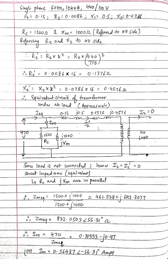
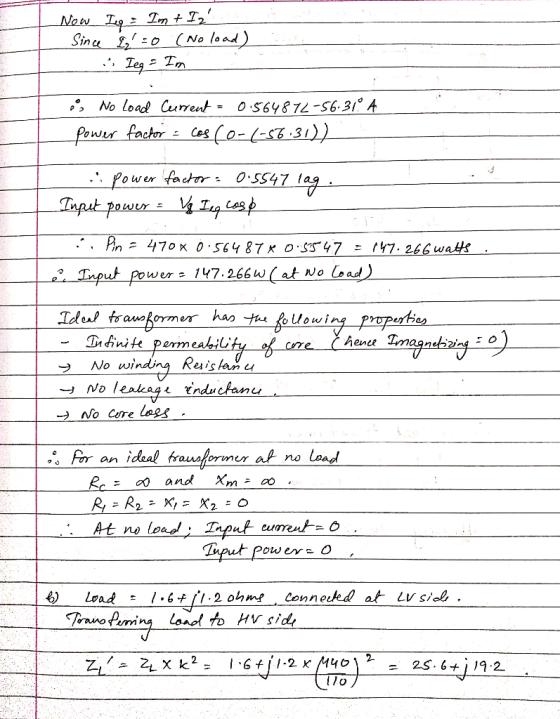
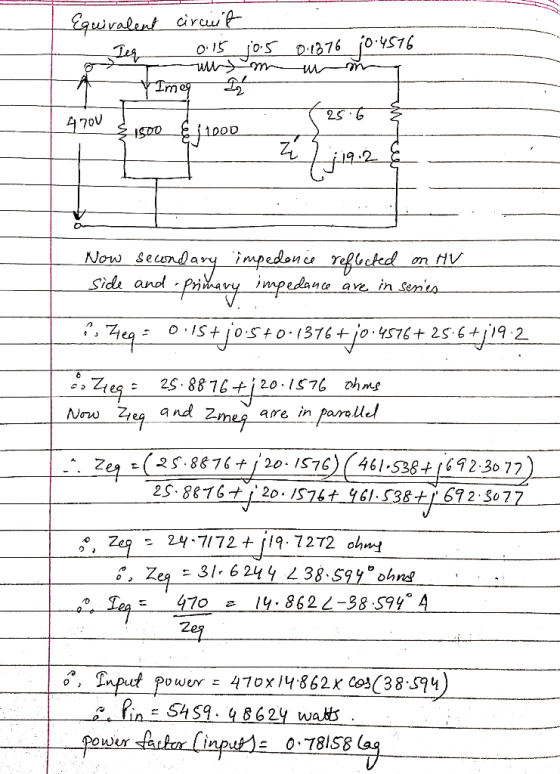
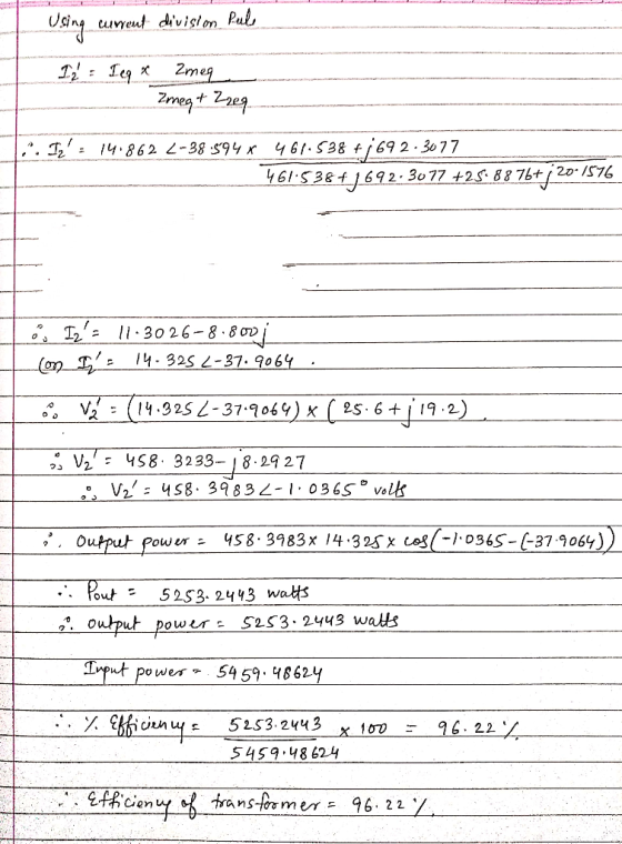
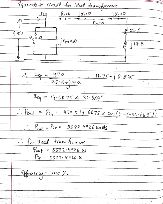
 Problem # 2-A single phase, 60 Hz, 10 KVA, 440/ 110 V has the following R1 0.15 R 0.0086X 0.5 X 0.0286 Re and Xnare 1500 and 1000 referred to the high voltage side Using the approximate equivalent circuit, Calculate the transformer no load power a- current, power factor and power when terminal voltage is 470 V. What would these values be if the transformer were ideal? b Calculate the transformeroutput power and eficiency when load of 1.6+j1.2 ohms is...
2.14 The resistances and leakage reactances of a 40-kVA 60-Hz 7.97-kV-V:240-V single-phase distribution transformer are where...
 2.14 The resistances and leakage reactances of a 40-kVA 60-Hz 7.97-kV-V:240-V single-phase distribution transformer are where subscript 1 denotes the 7.97-kV winding and subscript 2 denotes the 240-V winding. Each quantity is referred to its own side of the transformer. Consider a rated-kVA load connected at the low-voltage terminals. Assuming the load voltage to remain constant at 240 V use MATLAB to plot the high-side terminal voltage as a function of the power-factor angle as the load power factor varies...
6. A 20 kVA. 60 Hz, 8000/277 V transformer has the following impedances referred to the high volt...
 6. A 20 kVA. 60 Hz, 8000/277 V transformer has the following impedances referred to the high voltage side: Req-320, xe,-45Ω,R.-250kQ,Xm-30kQ. A) Calculate the voltage across rated load impedance with PF= 0.707 lagging when the transformer is connected to rated input voltage. B) Draw the phasor diagram showing the load voltage and current, voltage drop across the series impedance and voltage at the low voltage side of the ideal transformer, C) Calculate the efficiency of the transformer D) What adjustments...
3.10 A 240/120 V, 4.8 kVA, 60 Hz, single-phase transformer is used to supply a 4.8...
 3.10 A 240/120 V, 4.8 kVA, 60 Hz, single-phase transformer is used to supply a 4.8 kVA resistive load (i.e., the load has a power factor of 1.0) at rated voltage of 120 V a) If you assume the transformer is ideal, what would be the magni- tude of the expected primary side (240 V side) current? b) Again, if you assume the transformer is ideal, what is the apparent impedance of the load viewed from the high-voltage side of...
can you calculate this question and explain why? thanks 1. A 250-kVA, 11000/2200-V, 50-Hz, single-phase transformer...
 can you calculate this question and explain why?
thanks
1. A 250-kVA, 11000/2200-V, 50-Hz, single-phase transformer has the following parameters: RI 1.3 , R2 0.05 , Rel 193 k2, X1 4.5 Q X2 0.16 2 I,- 80 kQ Xml (a) Draw the approximate equivalent circuit of the transformer showing all the circuit parameters referred to the low-voltage side. Use the approximate equivalent circuit to calculate the input voltage and voltage regulation of the transformer when it delivers full load at...
can you calculate this question and explain why?
thanks
1. A 250-kVA, 11000/2200-V, 50-Hz, single-phase transformer has the following parameters: RI 1.3 , R2 0.05 , Rel 193 k2, X1 4.5 Q X2 0.16 2 I,- 80 kQ Xml (a) Draw the approximate equivalent circuit of the transformer showing all the circuit parameters referred to the low-voltage side. Use the approximate equivalent circuit to calculate the input voltage and voltage regulation of the transformer when it delivers full load at...
A 480 V, 60 Hz, 470 kVA, 0.85 PF lagging, 2-pole, Y-connected synchronous generator has a...
 A 480 V, 60 Hz, 470 kVA, 0.85 PF lagging, 2-pole,
Y-connected synchronous generator has a synchronous reactance of
XS=0.016 Ω and an armature resistance of RA=0.016 Ω. At rated
conditions the core losses are 7 kW. Friction losses and field
winding losses are 8 kW. Suppose the machine is connected to an
infinite bus (hence the terminal voltage is fixed) and it is
running at the rated conditions.
a) What is the rotor speed in rpm?
b) Calculate the...
A 480 V, 60 Hz, 470 kVA, 0.85 PF lagging, 2-pole,
Y-connected synchronous generator has a synchronous reactance of
XS=0.016 Ω and an armature resistance of RA=0.016 Ω. At rated
conditions the core losses are 7 kW. Friction losses and field
winding losses are 8 kW. Suppose the machine is connected to an
infinite bus (hence the terminal voltage is fixed) and it is
running at the rated conditions.
a) What is the rotor speed in rpm?
b) Calculate the...
 Problem # 2-A single phase, 60 Hz, 10 KVA, 440/ 110 V has the following R1 0.15 R 0.0086X 0.5 X 0.0286 Re and Xnare 1500 and 1000 referred to the high voltage side Using the approximate equivalent circuit, Calculate the transformer no load power a- current, power factor and power when terminal voltage is 470 V. What would these values be if the transformer were ideal? b Calculate the transformeroutput power and eficiency when load of 1.6+j1.2 ohms is...
 2.14 The resistances and leakage reactances of a 40-kVA 60-Hz 7.97-kV-V:240-V single-phase distribution transformer are where subscript 1 denotes the 7.97-kV winding and subscript 2 denotes the 240-V winding. Each quantity is referred to its own side of the transformer. Consider a rated-kVA load connected at the low-voltage terminals. Assuming the load voltage to remain constant at 240 V use MATLAB to plot the high-side terminal voltage as a function of the power-factor angle as the load power factor varies...
 6. A 20 kVA. 60 Hz, 8000/277 V transformer has the following impedances referred to the high voltage side: Req-320, xe,-45Ω,R.-250kQ,Xm-30kQ. A) Calculate the voltage across rated load impedance with PF= 0.707 lagging when the transformer is connected to rated input voltage. B) Draw the phasor diagram showing the load voltage and current, voltage drop across the series impedance and voltage at the low voltage side of the ideal transformer, C) Calculate the efficiency of the transformer D) What adjustments...
 3.10 A 240/120 V, 4.8 kVA, 60 Hz, single-phase transformer is used to supply a 4.8 kVA resistive load (i.e., the load has a power factor of 1.0) at rated voltage of 120 V a) If you assume the transformer is ideal, what would be the magni- tude of the expected primary side (240 V side) current? b) Again, if you assume the transformer is ideal, what is the apparent impedance of the load viewed from the high-voltage side of...
 can you calculate this question and explain why?
thanks
1. A 250-kVA, 11000/2200-V, 50-Hz, single-phase transformer has the following parameters: RI 1.3 , R2 0.05 , Rel 193 k2, X1 4.5 Q X2 0.16 2 I,- 80 kQ Xml (a) Draw the approximate equivalent circuit of the transformer showing all the circuit parameters referred to the low-voltage side. Use the approximate equivalent circuit to calculate the input voltage and voltage regulation of the transformer when it delivers full load at...
can you calculate this question and explain why?
thanks
1. A 250-kVA, 11000/2200-V, 50-Hz, single-phase transformer has the following parameters: RI 1.3 , R2 0.05 , Rel 193 k2, X1 4.5 Q X2 0.16 2 I,- 80 kQ Xml (a) Draw the approximate equivalent circuit of the transformer showing all the circuit parameters referred to the low-voltage side. Use the approximate equivalent circuit to calculate the input voltage and voltage regulation of the transformer when it delivers full load at...
 A 480 V, 60 Hz, 470 kVA, 0.85 PF lagging, 2-pole,
Y-connected synchronous generator has a synchronous reactance of
XS=0.016 Ω and an armature resistance of RA=0.016 Ω. At rated
conditions the core losses are 7 kW. Friction losses and field
winding losses are 8 kW. Suppose the machine is connected to an
infinite bus (hence the terminal voltage is fixed) and it is
running at the rated conditions.
a) What is the rotor speed in rpm?
b) Calculate the...
A 480 V, 60 Hz, 470 kVA, 0.85 PF lagging, 2-pole,
Y-connected synchronous generator has a synchronous reactance of
XS=0.016 Ω and an armature resistance of RA=0.016 Ω. At rated
conditions the core losses are 7 kW. Friction losses and field
winding losses are 8 kW. Suppose the machine is connected to an
infinite bus (hence the terminal voltage is fixed) and it is
running at the rated conditions.
a) What is the rotor speed in rpm?
b) Calculate the...
Most questions answered within 3 hours.
-
The manager at a car assembly plant believes that the mean
assembly time for a car...
asked 9 minutes ago -
Which of the following is true of electron capture?
A) It decreases the nuclide's mass number...
asked 1 hour ago -
Assuming an efficiency of 43.10%, calculate the actual yield of
magnesium nitrate formed from 114.9 g...
asked 2 hours ago -
The highly pathogenic bacterium Clostridium
perfringens causes gangrene, a disease that results in the
destruction of...
asked 4 hours ago -
In the context of situation analysis, which of the following is
a category for analysis in...
asked 4 hours ago -
In a study of the gas phase decomposition of sulfuryl chloride
at 600 K SO2Cl2(g)SO2(g) +...
asked 4 hours ago -
75 g of 2-propanol (C3H8O) and 25 g of pentane are mixed in a
200 mL...
asked 4 hours ago -
The 2800-turn coil in a dc motor has an area per turn of 1.1 ×
10-2...
asked 4 hours ago -
Draw a combinational logic circuit diagram with a symbol inside
the box for two I/P of...
asked 4 hours ago -
The cliché we use quite a lot in finance is: there is a need to
maximize...
asked 4 hours ago -
In class we discussed the addition of HCl to alpha pinene. Would
you expect one or...
asked 4 hours ago -
I'm trying to explain to my daughter to help her please help
me
I tagged the...
asked 4 hours ago