
Homework Answers

Add Answer to:
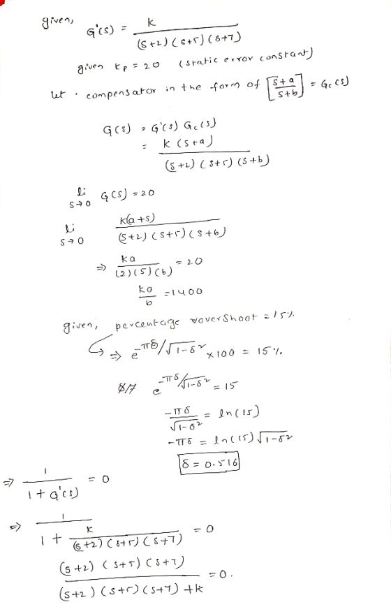
Problem 4 Suppose we have the system shown below operating at 15% overshoot. G(s)- (G) (s +2)%s +5%s+7) Use time domain techniques to design a compensator (and find K) so the appropriate static e...
Please answer this question showing all the steps. Problem 1 Suppose we have the system shown below operating at 1 0% overshoot. Go) +s+2)(+1 52 05123 120 Design changing the dominant pole locati...
 Please answer this question showing all the steps.
Problem 1 Suppose we have the system shown below operating at 1 0% overshoot. Go) +s+2)(+1 52 05123 120 Design changing the dominant pole locations of the uncompensated system a lag compensator so the appropriate static error constant is 5 without appreciably
Problem 1 Suppose we have the system shown below operating at 1 0% overshoot. Go) +s+2)(+1 52 05123 120 Design changing the dominant pole locations of the uncompensated system a...
Please answer this question showing all the steps.
Problem 1 Suppose we have the system shown below operating at 1 0% overshoot. Go) +s+2)(+1 52 05123 120 Design changing the dominant pole locations of the uncompensated system a lag compensator so the appropriate static error constant is 5 without appreciably
Problem 1 Suppose we have the system shown below operating at 1 0% overshoot. Go) +s+2)(+1 52 05123 120 Design changing the dominant pole locations of the uncompensated system a...
Problem (5): . The unity feedback system shown in Figure P9.1 with is operating with 10% overshoo...
 Problem (5): . The unity feedback system shown in Figure P9.1 with is operating with 10% overshoot [Section: 9 21 R. Whai is the value of the appropriate static error constant? b. Find the transfer function of a lag network so that the appropriale static error constant equals 4 without appreciably changing he dominant poles of the uncompensated system e. Use MATLAB or any other computer MATLAD progtam to si mulatcthe system o seethe effect of your compensator ML C(F)...
Design of PID compensator S. Design of PID (Proportional-plus-Integral and Derivative) Compensator ds/i (st3)(s+6 s+10) and...
 Design of PID compensator
S. Design of PID (Proportional-plus-Integral and Derivative) Compensator ds/i (st3)(s+6 s+10) and unity feedback Design a PID s+10) An uncompensated system has a gain controller so that the system can operate with a peak time that is two thirds that of the uncompensated system at 20% overshoot and with zero steady-state error for a step input. system has a gain Uncompensated system Compensated system K (s+8 G(s) = (s+3)(s+6)(s+10) ,H(s) = 1 20% OS; desired T,-23a...
Design of PID compensator
S. Design of PID (Proportional-plus-Integral and Derivative) Compensator ds/i (st3)(s+6 s+10) and unity feedback Design a PID s+10) An uncompensated system has a gain controller so that the system can operate with a peak time that is two thirds that of the uncompensated system at 20% overshoot and with zero steady-state error for a step input. system has a gain Uncompensated system Compensated system K (s+8 G(s) = (s+3)(s+6)(s+10) ,H(s) = 1 20% OS; desired T,-23a...
With explanation if possible, please 2. Design a lag compensator of the system in Figure 2 such that the static velocity error constant Kv is 40se ithout appreciably changing the original location (s...
 With explanation if possible, please
2. Design a lag compensator of the system in Figure 2 such that the static velocity error constant Kv is 40se ithout appreciably changing the original location (s--2+ j2V3) of a pair of the complex conjugate closed loop poles. Controller,0.25(S Ge(s) Figure 2
2. Design a lag compensator of the system in Figure 2 such that the static velocity error constant Kv is 40se ithout appreciably changing the original location (s--2+ j2V3) of a pair...
With explanation if possible, please
2. Design a lag compensator of the system in Figure 2 such that the static velocity error constant Kv is 40se ithout appreciably changing the original location (s--2+ j2V3) of a pair of the complex conjugate closed loop poles. Controller,0.25(S Ge(s) Figure 2
2. Design a lag compensator of the system in Figure 2 such that the static velocity error constant Kv is 40se ithout appreciably changing the original location (s--2+ j2V3) of a pair...
Please solve with detailed steps (NO MATLAB Solution).Thanks in advance 13. Consider the unity feedback system...
 Please solve with detailed steps (NO MATLAB
Solution).Thanks in advance
13. Consider the unity feedback system of Figure P9.1 with K G(s) s(s +20)(s +40) The system is operating at 20% overshoot. Design a compensator to decrease the settling time by a factor of 2 without affecting the percent overshoot and do the following: (Section: 9.3] a. Evaluate the uncompensated system's dominant poles, gain, and settling time. b. Evaluate the compensated system's dominant poles and settling time. c. Evaluate the...
Please solve with detailed steps (NO MATLAB
Solution).Thanks in advance
13. Consider the unity feedback system of Figure P9.1 with K G(s) s(s +20)(s +40) The system is operating at 20% overshoot. Design a compensator to decrease the settling time by a factor of 2 without affecting the percent overshoot and do the following: (Section: 9.3] a. Evaluate the uncompensated system's dominant poles, gain, and settling time. b. Evaluate the compensated system's dominant poles and settling time. c. Evaluate the...
Consider the sontrol system shown in the figure below: R(S) + E(s) C(s) K (s +...
 Consider the sontrol system shown in the figure below: R(S) + E(s) C(s) K (s + 4)(s + 6) g) Sketch the uncompensated system root locus showing all details. (5 Points) h) Find the dominant closed loop poles of the uncompensated system to operate with a 16.3% overshoot and peak time tp = 0.7255 (make sure to show this point on the Root Locus) (5 Points) (s+z) Now we want to design a PI compensator of the form to increase...
Find the dominant poles and gain K like they did in step 1 for the uncompensated system, EXCEPT D...
 Find the dominant poles and gain
K like they did in step 1 for the uncompensated
system, EXCEPT DO IT FOR 15% OVERSHOOT (zeta = 0.517) which is
121.13 degrees.
Show all work
Example 9.5 PID Controller Design PROBLEM: Given the system of Figure 9.31, design a PID controller so that the system can operate with a peak time that is two-thirds that of the uncompensated system at 20% overshoot and with zero steady-state error for a step input. R(s)Es)...
Find the dominant poles and gain
K like they did in step 1 for the uncompensated
system, EXCEPT DO IT FOR 15% OVERSHOOT (zeta = 0.517) which is
121.13 degrees.
Show all work
Example 9.5 PID Controller Design PROBLEM: Given the system of Figure 9.31, design a PID controller so that the system can operate with a peak time that is two-thirds that of the uncompensated system at 20% overshoot and with zero steady-state error for a step input. R(s)Es)...
For the control system shown below G(8) (8+10) 6+20) U(8) Y(8) H(s) = 1 design (using...
 For the control system shown below G(8) (8+10) 6+20) U(8) Y(8) H(s) = 1 design (using the Root-Locus Method) a compensator so that: • static velocity error constant K = 41 • the dumping ratio Efor dominant poles will remain unchanged, • a small change of undamped natural frequency oon is acceptable. sec For the control system shown below + G(S) = 820 s(8+10)(8+20) U(s) Y(s) H(s) = 1 design (using the Root-Locus Method) a LAG-LEAD compensator so that: •...
steps R(s) E(s) C(s) G(s) FIGURE P9.1 FIGURE P9.2 9. Consider the unity feedback system shown...
 steps
R(s) E(s) C(s) G(s) FIGURE P9.1 FIGURE P9.2 9. Consider the unity feedback system shown in Figure P9.1 with [Section: 9.3] K G(s) (s+4)3 a. Find the location of the dominant poles to yield a 1.6 second settling time and an overshoot of 25%. b. If a compensator with a zero at -1 is used to achieve the conditions of Part a, what must the angular contribution of the compensator pole be? c. Find the location of the compensator...
steps
R(s) E(s) C(s) G(s) FIGURE P9.1 FIGURE P9.2 9. Consider the unity feedback system shown in Figure P9.1 with [Section: 9.3] K G(s) (s+4)3 a. Find the location of the dominant poles to yield a 1.6 second settling time and an overshoot of 25%. b. If a compensator with a zero at -1 is used to achieve the conditions of Part a, what must the angular contribution of the compensator pole be? c. Find the location of the compensator...
Problem 4. Consider the control system shown below with plant G(s) that has time con- stants...
 Problem 4. Consider the control system shown below with plant G(s) that has time con- stants T1 = 2, T2 = 10, and gain k = 0.1. 4 673 +1679+1) (1.) Sketch the pole-zero plot for G(s). Is one of the poles more dominant? Using MATLAB, simulate the step response of the plant itself, along with G1(s) and G2(s) as defined by Gl(s) = and G2(s) = sti + 1 ST2+1 (2.) Design a proportional gain C(s) = K so...
 Please answer this question showing all the steps.
Problem 1 Suppose we have the system shown below operating at 1 0% overshoot. Go) +s+2)(+1 52 05123 120 Design changing the dominant pole locations of the uncompensated system a lag compensator so the appropriate static error constant is 5 without appreciably
Problem 1 Suppose we have the system shown below operating at 1 0% overshoot. Go) +s+2)(+1 52 05123 120 Design changing the dominant pole locations of the uncompensated system a...
Please answer this question showing all the steps.
Problem 1 Suppose we have the system shown below operating at 1 0% overshoot. Go) +s+2)(+1 52 05123 120 Design changing the dominant pole locations of the uncompensated system a lag compensator so the appropriate static error constant is 5 without appreciably
Problem 1 Suppose we have the system shown below operating at 1 0% overshoot. Go) +s+2)(+1 52 05123 120 Design changing the dominant pole locations of the uncompensated system a...
 Problem (5): . The unity feedback system shown in Figure P9.1 with is operating with 10% overshoot [Section: 9 21 R. Whai is the value of the appropriate static error constant? b. Find the transfer function of a lag network so that the appropriale static error constant equals 4 without appreciably changing he dominant poles of the uncompensated system e. Use MATLAB or any other computer MATLAD progtam to si mulatcthe system o seethe effect of your compensator ML C(F)...
 Design of PID compensator
S. Design of PID (Proportional-plus-Integral and Derivative) Compensator ds/i (st3)(s+6 s+10) and unity feedback Design a PID s+10) An uncompensated system has a gain controller so that the system can operate with a peak time that is two thirds that of the uncompensated system at 20% overshoot and with zero steady-state error for a step input. system has a gain Uncompensated system Compensated system K (s+8 G(s) = (s+3)(s+6)(s+10) ,H(s) = 1 20% OS; desired T,-23a...
Design of PID compensator
S. Design of PID (Proportional-plus-Integral and Derivative) Compensator ds/i (st3)(s+6 s+10) and unity feedback Design a PID s+10) An uncompensated system has a gain controller so that the system can operate with a peak time that is two thirds that of the uncompensated system at 20% overshoot and with zero steady-state error for a step input. system has a gain Uncompensated system Compensated system K (s+8 G(s) = (s+3)(s+6)(s+10) ,H(s) = 1 20% OS; desired T,-23a...
 With explanation if possible, please
2. Design a lag compensator of the system in Figure 2 such that the static velocity error constant Kv is 40se ithout appreciably changing the original location (s--2+ j2V3) of a pair of the complex conjugate closed loop poles. Controller,0.25(S Ge(s) Figure 2
2. Design a lag compensator of the system in Figure 2 such that the static velocity error constant Kv is 40se ithout appreciably changing the original location (s--2+ j2V3) of a pair...
With explanation if possible, please
2. Design a lag compensator of the system in Figure 2 such that the static velocity error constant Kv is 40se ithout appreciably changing the original location (s--2+ j2V3) of a pair of the complex conjugate closed loop poles. Controller,0.25(S Ge(s) Figure 2
2. Design a lag compensator of the system in Figure 2 such that the static velocity error constant Kv is 40se ithout appreciably changing the original location (s--2+ j2V3) of a pair...
 Please solve with detailed steps (NO MATLAB
Solution).Thanks in advance
13. Consider the unity feedback system of Figure P9.1 with K G(s) s(s +20)(s +40) The system is operating at 20% overshoot. Design a compensator to decrease the settling time by a factor of 2 without affecting the percent overshoot and do the following: (Section: 9.3] a. Evaluate the uncompensated system's dominant poles, gain, and settling time. b. Evaluate the compensated system's dominant poles and settling time. c. Evaluate the...
Please solve with detailed steps (NO MATLAB
Solution).Thanks in advance
13. Consider the unity feedback system of Figure P9.1 with K G(s) s(s +20)(s +40) The system is operating at 20% overshoot. Design a compensator to decrease the settling time by a factor of 2 without affecting the percent overshoot and do the following: (Section: 9.3] a. Evaluate the uncompensated system's dominant poles, gain, and settling time. b. Evaluate the compensated system's dominant poles and settling time. c. Evaluate the...
 Consider the sontrol system shown in the figure below: R(S) + E(s) C(s) K (s + 4)(s + 6) g) Sketch the uncompensated system root locus showing all details. (5 Points) h) Find the dominant closed loop poles of the uncompensated system to operate with a 16.3% overshoot and peak time tp = 0.7255 (make sure to show this point on the Root Locus) (5 Points) (s+z) Now we want to design a PI compensator of the form to increase...
 Find the dominant poles and gain
K like they did in step 1 for the uncompensated
system, EXCEPT DO IT FOR 15% OVERSHOOT (zeta = 0.517) which is
121.13 degrees.
Show all work
Example 9.5 PID Controller Design PROBLEM: Given the system of Figure 9.31, design a PID controller so that the system can operate with a peak time that is two-thirds that of the uncompensated system at 20% overshoot and with zero steady-state error for a step input. R(s)Es)...
Find the dominant poles and gain
K like they did in step 1 for the uncompensated
system, EXCEPT DO IT FOR 15% OVERSHOOT (zeta = 0.517) which is
121.13 degrees.
Show all work
Example 9.5 PID Controller Design PROBLEM: Given the system of Figure 9.31, design a PID controller so that the system can operate with a peak time that is two-thirds that of the uncompensated system at 20% overshoot and with zero steady-state error for a step input. R(s)Es)...
 For the control system shown below G(8) (8+10) 6+20) U(8) Y(8) H(s) = 1 design (using the Root-Locus Method) a compensator so that: • static velocity error constant K = 41 • the dumping ratio Efor dominant poles will remain unchanged, • a small change of undamped natural frequency oon is acceptable. sec For the control system shown below + G(S) = 820 s(8+10)(8+20) U(s) Y(s) H(s) = 1 design (using the Root-Locus Method) a LAG-LEAD compensator so that: •...
 steps
R(s) E(s) C(s) G(s) FIGURE P9.1 FIGURE P9.2 9. Consider the unity feedback system shown in Figure P9.1 with [Section: 9.3] K G(s) (s+4)3 a. Find the location of the dominant poles to yield a 1.6 second settling time and an overshoot of 25%. b. If a compensator with a zero at -1 is used to achieve the conditions of Part a, what must the angular contribution of the compensator pole be? c. Find the location of the compensator...
steps
R(s) E(s) C(s) G(s) FIGURE P9.1 FIGURE P9.2 9. Consider the unity feedback system shown in Figure P9.1 with [Section: 9.3] K G(s) (s+4)3 a. Find the location of the dominant poles to yield a 1.6 second settling time and an overshoot of 25%. b. If a compensator with a zero at -1 is used to achieve the conditions of Part a, what must the angular contribution of the compensator pole be? c. Find the location of the compensator...
 Problem 4. Consider the control system shown below with plant G(s) that has time con- stants T1 = 2, T2 = 10, and gain k = 0.1. 4 673 +1679+1) (1.) Sketch the pole-zero plot for G(s). Is one of the poles more dominant? Using MATLAB, simulate the step response of the plant itself, along with G1(s) and G2(s) as defined by Gl(s) = and G2(s) = sti + 1 ST2+1 (2.) Design a proportional gain C(s) = K so...
Most questions answered within 3 hours.
-
(63
#14)
which of the following statments best describes how chamging
the concentration of the substances...
asked 1 hour ago -
In the following reaction, which element is undergoing
oxidation: Na2SO3 + N2O --> N2 + Na2SO4...
asked 2 hours ago -
Which of the following pairs of ions have the same electron
configuration?
I: Br− and Se2−...
asked 4 hours ago -
The Foremost Composite Materials Company is planning a two-day
sales conference for October 19-20. The conference...
asked 4 hours ago -
3) Illustrate the observed pattern of relatedness of organisms
versus adaptations to specific conditions. This means...
asked 5 hours ago -
In winter a lake has a 0.35 m thick ice layer over 1.10 m of
water....
asked 6 hours ago -
Assuming the following has been encrypted with a Vigenere cipher
below, use the method(s) and assumptions...
asked 6 hours ago -
How would I use switch statements to write a program that will
take an input of...
asked 6 hours ago -
Imagine a reaction in which methane gas combusts at a constant
pressure of 1 atm and...
asked 6 hours ago -
Two parallel wires (each 12 m in length) are separated by a
distance of 0.065 m...
asked 6 hours ago -
Suppose there were three masses at the corner of uniform
equilateral triangle. The masses are m1...
asked 6 hours ago -
Situation: A building that is 618 m above the ground floor. How
many times would a...
asked 6 hours ago