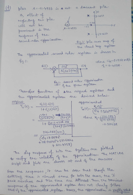
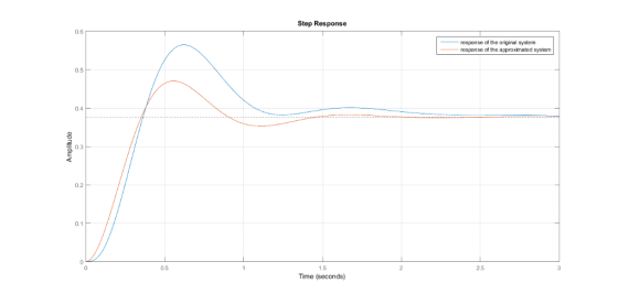
steps
![FIGURE P9.2 9. Consider the unity feedback system shown in Figure P9.1 with [Section: 9.3] K G(s) (s+4)3 a. Find the location](http://img.homeworklib.com/images/1734374e-c5b9-4a17-972f-9883a53be66d.png?x-oss-process=image/resize,w_560)
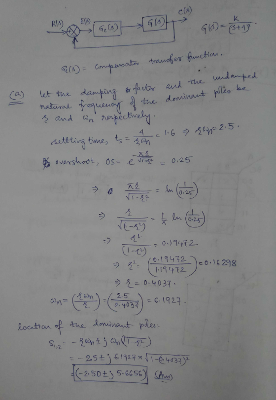
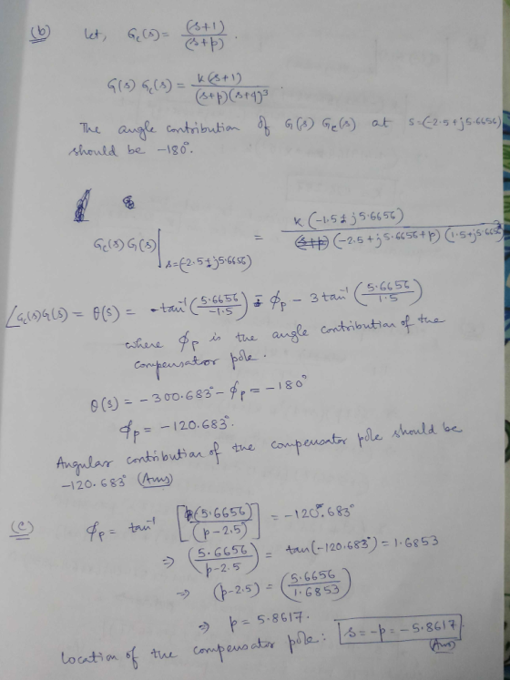
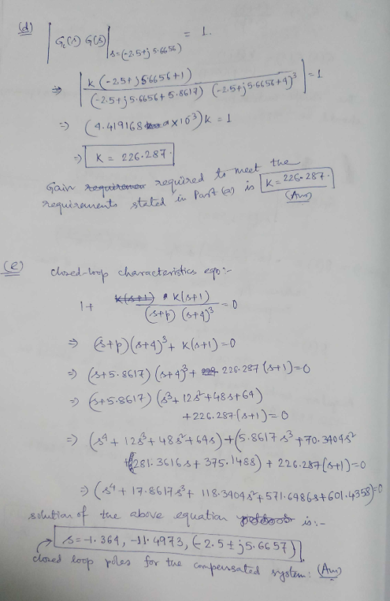
FIGURE P9.2 9. Consider the unity feedback system shown in Figure P9.1 with [Section: 9.3] K G(s) (s+4)3 a. Find the location of the dominant poles to yield a 1.6 second settling time and an overshoot of 25%. b. If a compensator with a zero at -1 is used to achieve the conditions of Part a, what must the angular contribution of the compensator pole be? c. Find the location of the compensator pole d. Find the gain required to meet the requirements stated in Part a. e. Find the location of other closed-loop poles for the compensated system f. Discuss the validity of your second-order approximation
Homework Answers
MATLAB SCRIPT:
clear all;
clc;
num1=[226.287 226.287];
den1=[1 17.8617 118.3404 571.6486 601.4358];
sys1=tf(num1,den1);
num2=[14.4286];
den2=[1 5 38.35];
sys2=tf(num2,den2);
step(sys1);hold on;grid
step(sys2)
legend('response of the original system','response of the
approximated system')
Response of the Systems:
Add Answer to:
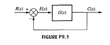
steps R(s) E(s) C(s) G(s) FIGURE P9.1 FIGURE P9.2 9. Consider the unity feedback system shown...
C(s) G(s) Figure 1: A block diagram for Problems 1-4 For the given unity feedback system with G(s...
 C(s) G(s) Figure 1: A block diagram for Problems 1-4 For the given unity feedback system with G(s) - s 5)3' (a) Find the location of the dominant poles to yield a 1.2 second settling time and overshoot of 15% (b) If a compensator with a zero at-1 is used to achieve the conditions of Part a, what must be the angular contribution of the compensator pole be? (c) Find the location of the compensator pole. (d) Find the gain...
Please solve with detailed steps (NO MATLAB Solution).Thanks in advance 13. Consider the unity feedback system...
 Please solve with detailed steps (NO MATLAB
Solution).Thanks in advance
13. Consider the unity feedback system of Figure P9.1 with K G(s) s(s +20)(s +40) The system is operating at 20% overshoot. Design a compensator to decrease the settling time by a factor of 2 without affecting the percent overshoot and do the following: (Section: 9.3] a. Evaluate the uncompensated system's dominant poles, gain, and settling time. b. Evaluate the compensated system's dominant poles and settling time. c. Evaluate the...
Please solve with detailed steps (NO MATLAB
Solution).Thanks in advance
13. Consider the unity feedback system of Figure P9.1 with K G(s) s(s +20)(s +40) The system is operating at 20% overshoot. Design a compensator to decrease the settling time by a factor of 2 without affecting the percent overshoot and do the following: (Section: 9.3] a. Evaluate the uncompensated system's dominant poles, gain, and settling time. b. Evaluate the compensated system's dominant poles and settling time. c. Evaluate the...
I8. Consider the unity feedback system of Figure P9.1 with G(s) s +3)(s +5) . Show...
 I8. Consider the unity feedback system of Figure P9.1 with G(s) s +3)(s +5) . Show that the system cannot operate with a settling time of 2/3 second and a percent over- shoot of 1.5 % with a simple gain adjustment. b. Design a lead compensator so that the system meets the transient response characteristics of Part a.Specify the compensator's pole, zero, and the required gain. R) Cu) FIGURE P9.1
22. For the unity feedback system given in Figure P9.1 with G(S) = 5(+ 5)(s +...
 22. For the unity feedback system given in Figure P9.1 with G(S) = 5(+ 5)(s + 11) do the following: [Section: 9.4] a. Find the gain, K, for the uncompensated system to operate with 30% overshoot. b. Find the peak time and K, for the uncompensated system, c. Design a lag-lead compensator to decrease the peak time by a factor of 2, decrease the percent overshoot by a factor of 2, and improve the steady-state error by a factor of...
4) 3s points 11. Given the unity feedback system of Figure P9.1 with G(s) K (s + 6) do the following: [Section: 9.3 a. Sketch the root locus. b) Using the operating point of -3.2+j2.38 find the g...
 4) 3s points 11. Given the unity feedback system of Figure P9.1 with G(s) K (s + 6) do the following: [Section: 9.3 a. Sketch the root locus. b) Using the operating point of -3.2+j2.38 find the gain K. c) if the system is to be cascade-compensated so that T, -1 sec, find the compensator compensator zero is at -45. pole if the d) Sketch the root locus for the new compensated system.
4) 3s points 11. Given the unity...
4) 3s points 11. Given the unity feedback system of Figure P9.1 with G(s) K (s + 6) do the following: [Section: 9.3 a. Sketch the root locus. b) Using the operating point of -3.2+j2.38 find the gain K. c) if the system is to be cascade-compensated so that T, -1 sec, find the compensator compensator zero is at -45. pole if the d) Sketch the root locus for the new compensated system.
4) 3s points 11. Given the unity...
Problem (5): . The unity feedback system shown in Figure P9.1 with is operating with 10% overshoo...
 Problem (5): . The unity feedback system shown in Figure P9.1 with is operating with 10% overshoot [Section: 9 21 R. Whai is the value of the appropriate static error constant? b. Find the transfer function of a lag network so that the appropriale static error constant equals 4 without appreciably changing he dominant poles of the uncompensated system e. Use MATLAB or any other computer MATLAD progtam to si mulatcthe system o seethe effect of your compensator ML C(F)...
Lag Compensator Design Using Root-Locus 2. Consider the unity feedback system in Figure 1 for G(s...
 Lag Compensator Design Using Root-Locus 2. Consider the unity feedback system in Figure 1 for G(s)- s(s+3(s6) Design a lag compensation to meet the following specifications The step response settling time is to be less than 5 sec. . The step response overshoot is to be less than 17% . The steady-state error to a unit ramp input must not exceed 10%. Dynamic specifications (overshoot and settling time) can be met using proportional feedback, but a lag compensator is needed...
3 .0.2) 0(z) ℉.20-1011,. +20s+101)(s+20) 20), the damping ratio for the dominant Problem 2: For a...
 3 .0.2) 0(z) ℉.20-1011,. +20s+101)(s+20) 20), the damping ratio for the dominant Problem 2: For a unity feedback system with closed loop poles is to be 0.4, and the settling time is to be 0.5 second for the compensated system. a. b. c. d. Find the coordinates of the dominant poles. Find the location of the compensator zero if the compensator pole is at -15 (lead compensator) Find the required system gain. Compare the performance of the uncompensated and compensated...
1. a. Plot the root loci for the unity-feedback system whose feed-forward transfer function is: G(s)...
 1. a. Plot the root loci for the unity-feedback system whose feed-forward transfer function is: G(s) = - s(s? + 4s + 8) If the value of K is set 8, where are the closed loop poles located? (5 Points) Hint: Non-dominant pole is an integer. b. Outline the procedure for design of a lag compensator (on the forward path) that cuts down the rise and settling times to half of the dominant second order system in 1. a. (3...
Compensator Plant 100 R(s) sta Y(s) For the unity feedback system shown in Fig. 3.55, specify t...
 Compensator Plant 100 R(s) sta Y(s) For the unity feedback system shown in Fig. 3.55, specify the gain and pole location of the compensator so that the overall closed-loop response to a unit- step input has an overshoot of no more than 30%, and a 2% settling time of no more than 0.2 sec. Verify your design using Matlab. 3.27
Compensator Plant 100 R(s) sta Y(s)
For the unity feedback system shown in Fig. 3.55, specify the gain and pole...
Compensator Plant 100 R(s) sta Y(s) For the unity feedback system shown in Fig. 3.55, specify the gain and pole location of the compensator so that the overall closed-loop response to a unit- step input has an overshoot of no more than 30%, and a 2% settling time of no more than 0.2 sec. Verify your design using Matlab. 3.27
Compensator Plant 100 R(s) sta Y(s)
For the unity feedback system shown in Fig. 3.55, specify the gain and pole...
 C(s) G(s) Figure 1: A block diagram for Problems 1-4 For the given unity feedback system with G(s) - s 5)3' (a) Find the location of the dominant poles to yield a 1.2 second settling time and overshoot of 15% (b) If a compensator with a zero at-1 is used to achieve the conditions of Part a, what must be the angular contribution of the compensator pole be? (c) Find the location of the compensator pole. (d) Find the gain...
 Please solve with detailed steps (NO MATLAB
Solution).Thanks in advance
13. Consider the unity feedback system of Figure P9.1 with K G(s) s(s +20)(s +40) The system is operating at 20% overshoot. Design a compensator to decrease the settling time by a factor of 2 without affecting the percent overshoot and do the following: (Section: 9.3] a. Evaluate the uncompensated system's dominant poles, gain, and settling time. b. Evaluate the compensated system's dominant poles and settling time. c. Evaluate the...
Please solve with detailed steps (NO MATLAB
Solution).Thanks in advance
13. Consider the unity feedback system of Figure P9.1 with K G(s) s(s +20)(s +40) The system is operating at 20% overshoot. Design a compensator to decrease the settling time by a factor of 2 without affecting the percent overshoot and do the following: (Section: 9.3] a. Evaluate the uncompensated system's dominant poles, gain, and settling time. b. Evaluate the compensated system's dominant poles and settling time. c. Evaluate the...
 I8. Consider the unity feedback system of Figure P9.1 with G(s) s +3)(s +5) . Show that the system cannot operate with a settling time of 2/3 second and a percent over- shoot of 1.5 % with a simple gain adjustment. b. Design a lead compensator so that the system meets the transient response characteristics of Part a.Specify the compensator's pole, zero, and the required gain. R) Cu) FIGURE P9.1
 22. For the unity feedback system given in Figure P9.1 with G(S) = 5(+ 5)(s + 11) do the following: [Section: 9.4] a. Find the gain, K, for the uncompensated system to operate with 30% overshoot. b. Find the peak time and K, for the uncompensated system, c. Design a lag-lead compensator to decrease the peak time by a factor of 2, decrease the percent overshoot by a factor of 2, and improve the steady-state error by a factor of...
 4) 3s points 11. Given the unity feedback system of Figure P9.1 with G(s) K (s + 6) do the following: [Section: 9.3 a. Sketch the root locus. b) Using the operating point of -3.2+j2.38 find the gain K. c) if the system is to be cascade-compensated so that T, -1 sec, find the compensator compensator zero is at -45. pole if the d) Sketch the root locus for the new compensated system.
4) 3s points 11. Given the unity...
4) 3s points 11. Given the unity feedback system of Figure P9.1 with G(s) K (s + 6) do the following: [Section: 9.3 a. Sketch the root locus. b) Using the operating point of -3.2+j2.38 find the gain K. c) if the system is to be cascade-compensated so that T, -1 sec, find the compensator compensator zero is at -45. pole if the d) Sketch the root locus for the new compensated system.
4) 3s points 11. Given the unity...
 Problem (5): . The unity feedback system shown in Figure P9.1 with is operating with 10% overshoot [Section: 9 21 R. Whai is the value of the appropriate static error constant? b. Find the transfer function of a lag network so that the appropriale static error constant equals 4 without appreciably changing he dominant poles of the uncompensated system e. Use MATLAB or any other computer MATLAD progtam to si mulatcthe system o seethe effect of your compensator ML C(F)...
 Lag Compensator Design Using Root-Locus 2. Consider the unity feedback system in Figure 1 for G(s)- s(s+3(s6) Design a lag compensation to meet the following specifications The step response settling time is to be less than 5 sec. . The step response overshoot is to be less than 17% . The steady-state error to a unit ramp input must not exceed 10%. Dynamic specifications (overshoot and settling time) can be met using proportional feedback, but a lag compensator is needed...
 3 .0.2) 0(z) ℉.20-1011,. +20s+101)(s+20) 20), the damping ratio for the dominant Problem 2: For a unity feedback system with closed loop poles is to be 0.4, and the settling time is to be 0.5 second for the compensated system. a. b. c. d. Find the coordinates of the dominant poles. Find the location of the compensator zero if the compensator pole is at -15 (lead compensator) Find the required system gain. Compare the performance of the uncompensated and compensated...
 1. a. Plot the root loci for the unity-feedback system whose feed-forward transfer function is: G(s) = - s(s? + 4s + 8) If the value of K is set 8, where are the closed loop poles located? (5 Points) Hint: Non-dominant pole is an integer. b. Outline the procedure for design of a lag compensator (on the forward path) that cuts down the rise and settling times to half of the dominant second order system in 1. a. (3...
 Compensator Plant 100 R(s) sta Y(s) For the unity feedback system shown in Fig. 3.55, specify the gain and pole location of the compensator so that the overall closed-loop response to a unit- step input has an overshoot of no more than 30%, and a 2% settling time of no more than 0.2 sec. Verify your design using Matlab. 3.27
Compensator Plant 100 R(s) sta Y(s)
For the unity feedback system shown in Fig. 3.55, specify the gain and pole...
Compensator Plant 100 R(s) sta Y(s) For the unity feedback system shown in Fig. 3.55, specify the gain and pole location of the compensator so that the overall closed-loop response to a unit- step input has an overshoot of no more than 30%, and a 2% settling time of no more than 0.2 sec. Verify your design using Matlab. 3.27
Compensator Plant 100 R(s) sta Y(s)
For the unity feedback system shown in Fig. 3.55, specify the gain and pole...
Most questions answered within 3 hours.
-
Why are polymers not typically casted into products?
asked 13 minutes ago -
When rolling a die 129 times, what is the probability of rolling
a 6 no more...
asked 30 minutes ago -
4. A call option currently sells for $7.75. It has a strike
price of $85 and...
asked 19 minutes ago -
1.
You need to prepare 10.0 liters of an acid aqueous solution with a
pH of...
asked 21 minutes ago -
Along an aggregate supply curve, if the level of output is less
than the natural level...
asked 22 minutes ago -
By 2025, annual consumption in emerging markets will total $30
trillion and contribute more than ________...
asked 27 minutes ago -
At what point does reformation cease to be a viable option for
those who are oppressed...
asked 31 minutes ago -
Place letters corresponding to amounts in the proper order for
lightest to heaviest samples:
a) 2100...
asked 35 minutes ago -
Consider the multicore processor with 6 heterogeneous cores
labelled C1, C2, C3, C4, C5, and C6....
asked 38 minutes ago -
Document system components according to standards and procedures
(Implement and hand over system components) IT administrative
asked 38 minutes ago -
The college asked 700 students if they wanted a longer spring
break and 600 students said...
asked 38 minutes ago -
Determine the temperature (in Celsius) at which 1.00 mole of an
ideal gas will have a...
asked 1 hour ago