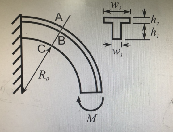
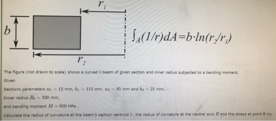
T" A(1/r)dA=b-In(r/r The figure (not drawn to scale) shows a curved I-beam of given section and inner radius subjected to a bending moment. Given Sections parameters w 12 mm, h 115 mm, w85mm and he 21 mm, Inner radlus Ro320 mm, and bending moment M 850 MPa Calculate the radius of curvature at the beam's section centroid F, the radius of curvature at the neutral axis R and the stress at point Bop
Homework Answers


Add Answer to:
2 1 0 T" A(1/r)dA=b-In(r/r The figure (not drawn to scale) shows a curved I-beam of given section and inner rad...
The Question The above figure (not drawn to scale) shows a rectangular beam with a depth...
 The Question The above figure (not drawn to scale) shows a rectangular beam with a depth of d = 32mm and breadth of b = 50mm subjected to a combined loading of F = 50kN direct load and M-150Nm bending load. The bending moment is acting about the depth of the beam (causing it to bend about its depth, d). Calculate the second moment of area, I, in m in the form ax 10"" where the number a is correct...
Figure 2a shows a composite beam made by placing three steel plates inside a wooden section....
 Figure 2a shows a composite beam made by placing three
steel plates inside a wooden
section.
(a) Determine the maximum bending stress developed in the wooden
section and steel plate
if the beam is subjected to allowable bending moment, M of 20 kN.m.
Given that the
Modulus of Elasticity of wood is 13.1 GPa and steel is 200
GPa.
[14 Marks]
Figure 2a: Composite beam
(b) Figure 2b shows another beam without steel plates. Suggest the
maximum bending
stress for...
Figure 2a shows a composite beam made by placing three
steel plates inside a wooden
section.
(a) Determine the maximum bending stress developed in the wooden
section and steel plate
if the beam is subjected to allowable bending moment, M of 20 kN.m.
Given that the
Modulus of Elasticity of wood is 13.1 GPa and steel is 200
GPa.
[14 Marks]
Figure 2a: Composite beam
(b) Figure 2b shows another beam without steel plates. Suggest the
maximum bending
stress for...
4B and the beam cross-section is shown in Figure Q3 (b) The yield stress of the...
 4B and the beam cross-section is shown in Figure Q3 (b) The yield stress of the material is 250 MPs and the material behaves linearly elastic-perfectly plastic. Figure Q3 (a) shows an overhanging beam ABC subjected to a uniformly distributed load w along a) Sketch the bending moment dingram of the beam b) Calculate the magnitade of moment that causes a plastic hinge (fully plastic) in the cross section Find the magnitude of w during plastic hinge at the most...
The simply-supported beam having I-beam cross-section as shown in figure is to carry a uniformly distributed...
 The simply-supported beam having I-beam cross-section as shown in figure is to carry a uniformly distributed load over its entire 1.2m length. Specify the maximum allowable load if the beam is made from malleable iron, ASTM A220, class 80002. The allowable tensile stress is 164 MPa and allowable compressive stress is 412 MPa. The centroid of the section is located at 35 mm from the bottom and moment of inertia are Ix = 2.66 x 10 mm". (a) Draw loading...
Hi, could you please provide a clear and easy to follow worked solution for the following questions. I will leave feedba...
 Hi,
could you please provide a clear and easy to follow worked
solution for the following questions. I will leave feedback that
reflects the quality of your response.
The correct answers are
21.0kN.m
50.2MPa and 38.7MPa
22.6kN.m
A beam with the section illustrated in the figure below is subjected to pure bending with compressive stresses induced above the neutral axis. The beam is steel with a yield strength of 450 MPa, modulus of elasticity of 210 GPa and Poisson's ratio...
Hi,
could you please provide a clear and easy to follow worked
solution for the following questions. I will leave feedback that
reflects the quality of your response.
The correct answers are
21.0kN.m
50.2MPa and 38.7MPa
22.6kN.m
A beam with the section illustrated in the figure below is subjected to pure bending with compressive stresses induced above the neutral axis. The beam is steel with a yield strength of 450 MPa, modulus of elasticity of 210 GPa and Poisson's ratio...
The cross-sectional dimensions of the beam shown in the figure are r, = 115 mm and...
 The cross-sectional dimensions of the beam shown in the figure are r, = 115 mm and r; = 89 mm. Given M, = 20 kN.m, a = 26°, and B = 50°, what are the bending stresses at points Hand K? H a Part 1 Find the area moment of inertia for the cross-section about the Z axis. 1,= i mm e Textbook and Media Hint Save for Later Attempts: unlimited Submit Answer Part 2 Find the y coordinates of...
2. AT-beam with dimensions b 175 mm, t 14 mm, h -250 mm, and hi =...
 2. AT-beam with dimensions b 175 mm, t 14 mm, h -250 mm, and hi = 230 mm is subjected to a shear force V= 84 kN. For this problem, assume the cross-section can be discretized into two rectangles (the web and the flange (a) Determine the moment of inertia of the cross section about the (b) Determine the shear stress at the neutral axis, TNA (c) Determine the shear stress at the interface of the web and the flange,...
3. A beam with a hollow circular cross section of outer diameter D and inner diameter...
 3. A beam with a hollow circular cross section of outer diameter D and inner diameter d. The length Lis fixed at a wall. Consider the following loading conditions, all applied to the beam at the midpoint of length L. For each loading scheme state determine the magnitude of that stress in terms of the variables given in the problem). (5 points) i. ii. iii. iv. V. Normal stress due to axial load F Shear stress due to torque T...
The cross-sectional dimensions of the beam shown in the figure are r, = 107 mm and...
 The cross-sectional dimensions of the beam shown in the figure are r, = 107 mm and ri = 89 mm. Given M, = 19 kN.m, a = 37° , and B = 49°, what are the bending stresses at points H and K? y H a r; *Part 1 Find the area moment of inertia for the cross-section about the z axis. 1, = *1 mm4 the tolerance is +/-4% *Part 2 Find the y coordinates of points H and...
The cross-sectional dimensions of the beam shown in the figure are r, = 125 mm and...
 The cross-sectional dimensions of the beam shown in the figure are r, = 125 mm and r, = 81 mm. Given M. = 13 kN.m, a = 316, and B = 45, what are the bending stresses at points Hand K? H/ Part 1 Find the area moment of inertia for the cross-section about the z axis. I. y Part 2 Find the y coordinates of points Hand K. mm ya mm Click if you would like to Show Work...
 The Question The above figure (not drawn to scale) shows a rectangular beam with a depth of d = 32mm and breadth of b = 50mm subjected to a combined loading of F = 50kN direct load and M-150Nm bending load. The bending moment is acting about the depth of the beam (causing it to bend about its depth, d). Calculate the second moment of area, I, in m in the form ax 10"" where the number a is correct...
 Figure 2a shows a composite beam made by placing three
steel plates inside a wooden
section.
(a) Determine the maximum bending stress developed in the wooden
section and steel plate
if the beam is subjected to allowable bending moment, M of 20 kN.m.
Given that the
Modulus of Elasticity of wood is 13.1 GPa and steel is 200
GPa.
[14 Marks]
Figure 2a: Composite beam
(b) Figure 2b shows another beam without steel plates. Suggest the
maximum bending
stress for...
Figure 2a shows a composite beam made by placing three
steel plates inside a wooden
section.
(a) Determine the maximum bending stress developed in the wooden
section and steel plate
if the beam is subjected to allowable bending moment, M of 20 kN.m.
Given that the
Modulus of Elasticity of wood is 13.1 GPa and steel is 200
GPa.
[14 Marks]
Figure 2a: Composite beam
(b) Figure 2b shows another beam without steel plates. Suggest the
maximum bending
stress for...
 4B and the beam cross-section is shown in Figure Q3 (b) The yield stress of the material is 250 MPs and the material behaves linearly elastic-perfectly plastic. Figure Q3 (a) shows an overhanging beam ABC subjected to a uniformly distributed load w along a) Sketch the bending moment dingram of the beam b) Calculate the magnitade of moment that causes a plastic hinge (fully plastic) in the cross section Find the magnitude of w during plastic hinge at the most...
 The simply-supported beam having I-beam cross-section as shown in figure is to carry a uniformly distributed load over its entire 1.2m length. Specify the maximum allowable load if the beam is made from malleable iron, ASTM A220, class 80002. The allowable tensile stress is 164 MPa and allowable compressive stress is 412 MPa. The centroid of the section is located at 35 mm from the bottom and moment of inertia are Ix = 2.66 x 10 mm". (a) Draw loading...
 Hi,
could you please provide a clear and easy to follow worked
solution for the following questions. I will leave feedback that
reflects the quality of your response.
The correct answers are
21.0kN.m
50.2MPa and 38.7MPa
22.6kN.m
A beam with the section illustrated in the figure below is subjected to pure bending with compressive stresses induced above the neutral axis. The beam is steel with a yield strength of 450 MPa, modulus of elasticity of 210 GPa and Poisson's ratio...
Hi,
could you please provide a clear and easy to follow worked
solution for the following questions. I will leave feedback that
reflects the quality of your response.
The correct answers are
21.0kN.m
50.2MPa and 38.7MPa
22.6kN.m
A beam with the section illustrated in the figure below is subjected to pure bending with compressive stresses induced above the neutral axis. The beam is steel with a yield strength of 450 MPa, modulus of elasticity of 210 GPa and Poisson's ratio...
 The cross-sectional dimensions of the beam shown in the figure are r, = 115 mm and r; = 89 mm. Given M, = 20 kN.m, a = 26°, and B = 50°, what are the bending stresses at points Hand K? H a Part 1 Find the area moment of inertia for the cross-section about the Z axis. 1,= i mm e Textbook and Media Hint Save for Later Attempts: unlimited Submit Answer Part 2 Find the y coordinates of...
 2. AT-beam with dimensions b 175 mm, t 14 mm, h -250 mm, and hi = 230 mm is subjected to a shear force V= 84 kN. For this problem, assume the cross-section can be discretized into two rectangles (the web and the flange (a) Determine the moment of inertia of the cross section about the (b) Determine the shear stress at the neutral axis, TNA (c) Determine the shear stress at the interface of the web and the flange,...
 3. A beam with a hollow circular cross section of outer diameter D and inner diameter d. The length Lis fixed at a wall. Consider the following loading conditions, all applied to the beam at the midpoint of length L. For each loading scheme state determine the magnitude of that stress in terms of the variables given in the problem). (5 points) i. ii. iii. iv. V. Normal stress due to axial load F Shear stress due to torque T...
 The cross-sectional dimensions of the beam shown in the figure are r, = 107 mm and ri = 89 mm. Given M, = 19 kN.m, a = 37° , and B = 49°, what are the bending stresses at points H and K? y H a r; *Part 1 Find the area moment of inertia for the cross-section about the z axis. 1, = *1 mm4 the tolerance is +/-4% *Part 2 Find the y coordinates of points H and...
 The cross-sectional dimensions of the beam shown in the figure are r, = 125 mm and r, = 81 mm. Given M. = 13 kN.m, a = 316, and B = 45, what are the bending stresses at points Hand K? H/ Part 1 Find the area moment of inertia for the cross-section about the z axis. I. y Part 2 Find the y coordinates of points Hand K. mm ya mm Click if you would like to Show Work...
Most questions answered within 3 hours.
-
Jor-el throws a ball upward from the top of a 728 foot building
on the planet...
asked 1 minute from now -
Draw the Lewis dot structures for the following molecules. None
of the atoms have a formal...
asked 15 seconds ago -
What does it mean when an element is radioactive?
a.
It means the element is changing...
asked 47 seconds ago -
A company deposits $6,000 in a bank at the end of every year for
10 years....
asked 15 seconds ago -
What are some strategies for eliminating service barriers?
By using your knowledge of
behavioral styles, please...
asked 8 minutes ago -
What are the decimal numbers for 159, 150, 200, 113, 225, 87,
106, 81 when converted...
asked 16 minutes ago -
Calculate and plot the number and weight distributions of x-mers
found in a step-growth polymerization for...
asked 36 minutes ago -
The Baily Corporation has developed a specialized software
program that improves inventory control capability. The following...
asked 39 minutes ago -
Problem 5-4A (Part Level Submission) Wolford Department Store is
located in midtown Metropolis. During the past...
asked 39 minutes ago -
Preparation of Benzoic Acid using a Grignard Reagent URGENT
1. During your Grignard formation, a small...
asked 1 hour ago -
A uniform magnetic field is perpendicular to the plane of a wire
loop. If the loop...
asked 1 hour ago -
At the peak of your career, your were earning $120,000 and
holding a top level position....
asked 1 hour ago