
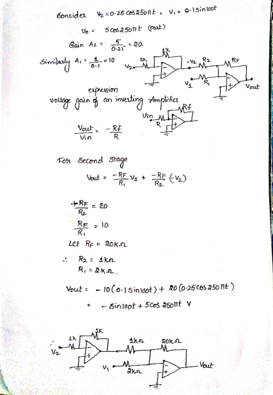
QUESTION 2
You are asked to design an electronic circuit using operational amplifiers. There are two inputs to the circuit, \(V_{1}=0.1 \sin 100 t V\), and \(V_{2}=0.25 \cos 250 \pi t V\). The output of the circuit is required to be:
$$ V_{0}=-\sin 100 t+5 \cos 250 \pi t V $$
a. Draw diagram of the circuit you designed.
b. Calculate the values of the components.
QUESTION 3
An inverting circuit is shown in the figure.
a. Derive an expression for \( v_{x} / v_{1}\)
b. Derive an expression for \(v_{o} / v_{x}\).
C. Derive the expression for the voltage gain vo/v1
Homework Answers


Add Answer to:
QUESTION 2 (15 Points) You are asked to design an electronic circuit using operational amplifiers. There are two inputs...
Problem 52: (25 points) Operational amplifiers are important building blocks in a wide spectrum of electronic systems such as amplifiers and filters. The concept of feedback control is of central imp...
 Problem 52: (25 points) Operational amplifiers are important building blocks in a wide spectrum of electronic systems such as amplifiers and filters. The concept of feedback control is of central importance in understanding the design of operational amplifier circuits. For without feedback, operational amplifiers behave as comparators. This problem shows why it is necessary to connect the output of an operational amplifier to its inverting input. Negative feedback produces a circuit that is BIBO stable. Figure 1(A) shows the circuit...
Given below is a differential operational amplifier in block form and its internal transistor circuit with...
 Given below is a differential operational amplifier in block
form and its internal transistor circuit with VCC=20V, VEE= 12 V ,
RC=5kΩ,RE=1kΩ and R1=2kΩ. Assume that the transistors are identical
and have a βac=βdc=100. An ac signal Vi(t)=5sin(10t) is applied to
the input terminals where Terminal 1 is Positive (non-invertinq)
& Terminal 2 is negative (inverting) as stated in the cases
below. Draw the output signals in each case.
: a) V1=Vi(t) , V2=Grounded. Vo(t)=Vo2-Vo1 )
b) V1=Grounded , V2=Vi(t)....
Given below is a differential operational amplifier in block
form and its internal transistor circuit with VCC=20V, VEE= 12 V ,
RC=5kΩ,RE=1kΩ and R1=2kΩ. Assume that the transistors are identical
and have a βac=βdc=100. An ac signal Vi(t)=5sin(10t) is applied to
the input terminals where Terminal 1 is Positive (non-invertinq)
& Terminal 2 is negative (inverting) as stated in the cases
below. Draw the output signals in each case.
: a) V1=Vi(t) , V2=Grounded. Vo(t)=Vo2-Vo1 )
b) V1=Grounded , V2=Vi(t)....
Question 1 (15 points) Consider the circuit below with vi as the input and v, as...
 Question 1 (15 points) Consider the circuit below with vi as the input and v, as the output. Let the component values be R = 1001 and C = 1000F. C + v;(t) vo(t) Answer the following questions using the formulas from the lecture slides: 1. What is the type of this filter? (1 points) 2. Write down the expression for the transfer function H(w) of the circuit. (4 points) 3. Write down the expression for frequency response |H(w) of...
QUESTION 6 In an inverting summing amplifier circuit, two inputs are given (check here to show):...
 QUESTION 6 In an inverting summing amplifier circuit, two inputs are given (check here to show): V1 peak - 2.0 V (square) and V2peak = 1.0 V (triangle) at 500 Hz Draw one cycle of V1, V2 and Vout on the V-t graph paper (here) when R1 - R2. After complete your drawings, write your name on the graph, take a photo or save it to a jpg file and submit below Attach File Browse My Computer Browse Content Collection...
**ONLY C&D PLEASE!** (100 points) You are asked to design a "HELLO" circuit in this question....
 **ONLY C&D PLEASE!**
(100 points) You are asked to design a "HELLO" circuit in this question. The inputs of the circuit are three bits x, y and z. The outputs are seven bits a, b, c, d, e, f and g controlling a 7-segment display (see Fig. 2.63(a)). For the 7-segment display, a segment is turned on when the corresponding control signal is 1. The "HELLO" circuit outputs the control signals to display the letter "H", "E", "L", "L", "O"...
**ONLY C&D PLEASE!**
(100 points) You are asked to design a "HELLO" circuit in this question. The inputs of the circuit are three bits x, y and z. The outputs are seven bits a, b, c, d, e, f and g controlling a 7-segment display (see Fig. 2.63(a)). For the 7-segment display, a segment is turned on when the corresponding control signal is 1. The "HELLO" circuit outputs the control signals to display the letter "H", "E", "L", "L", "O"...
The equations for the charge Q(t) and current i (t) in the following LRC circuit are Question 3 (...
 3
The equations for the charge Q(t) and current i (t) in the following LRC circuit are Question 3 (5 points) Saved 0 amps dt C 10 amps i(t) dt 10 amps where the applied voltage VA -Vp V cos at as soon as the switch S is closed at t 0 Question 4 (5 points Saved ift) 10 amps -10 amps 0 amps Qrt The general solution is: please hand in at your recitation, the graphs of when Q(0)-i(0-0,...
3
The equations for the charge Q(t) and current i (t) in the following LRC circuit are Question 3 (5 points) Saved 0 amps dt C 10 amps i(t) dt 10 amps where the applied voltage VA -Vp V cos at as soon as the switch S is closed at t 0 Question 4 (5 points Saved ift) 10 amps -10 amps 0 amps Qrt The general solution is: please hand in at your recitation, the graphs of when Q(0)-i(0-0,...
Question 2 (20 points) Consider the circuit below with Vị as the input and v, as...
 Question 2 (20 points) Consider the circuit below with Vị as the input and v, as the output. Let the component values be R = 33.2, C = 470uF and L = 250mH. R + + yo(t) L - Answer the following questions using the formulas from the lecture slides: 1. What is the type of this filter? (2 points) 2. Write down the expression for the transfer function H(w) of the circuit. (4 points) 3. Write down the expression...
Review Qns 2 - ME 344 Instrumentation &Measurements Question 1: A simple Wheatstone bridge has ar...
 Answers for q 2,3 and 4 asap please !?
Review Qns 2 - ME 344 Instrumentation &Measurements Question 1: A simple Wheatstone bridge has arms of R 1212, R2 1192, and R,-1212. What is the value of R4 for balance? If R4-122 and the bridge is driven with a source at 100 V, what is the open-circuit output voltage? (123.0 Ω, 100 V, 0.21 V) Question 2: A capacitive transducer uses two quartz diaphragms of area 600 mm2 separated by...
Answers for q 2,3 and 4 asap please !?
Review Qns 2 - ME 344 Instrumentation &Measurements Question 1: A simple Wheatstone bridge has arms of R 1212, R2 1192, and R,-1212. What is the value of R4 for balance? If R4-122 and the bridge is driven with a source at 100 V, what is the open-circuit output voltage? (123.0 Ω, 100 V, 0.21 V) Question 2: A capacitive transducer uses two quartz diaphragms of area 600 mm2 separated by...
QUESTION 2 You are attempting to implement a NOR gate by using the BJT circuit shown...
 QUESTION 2 You are attempting to implement a NOR gate by using the BJT circuit shown in Figure 2. Note that the two BJTs are identical. Vec 3V • VOLT R RS w A w B OL Figure 2: NOR gate implementation There are two operational requirements that you need to achieve: The required output voltage thresholds are: Von = 2.4 and VoL = 0.4. The current load at the base cannot exceed a certain value, i.e. Is s 1(max)...
Just solved (Task 2) Just solved (Task 2) Just solved (Task 2) You work as a...
 Just solved (Task 2)
Just solved (Task 2)
You work as a technical engineer in a company that designs and installs sound systeins, such as speakers for large halls and open spaces. The company manager has assigned you to design a new sound system for a stadiun, and asked you to make a technical report explaining some preliminary studies on the behaviour of sound waves. Task 1: A When we are designing the sound levels to...
Just solved (Task 2)
Just solved (Task 2)
Just solved (Task 2)
You work as a technical engineer in a company that designs and installs sound systeins, such as speakers for large halls and open spaces. The company manager has assigned you to design a new sound system for a stadiun, and asked you to make a technical report explaining some preliminary studies on the behaviour of sound waves. Task 1: A When we are designing the sound levels to...
 Problem 52: (25 points) Operational amplifiers are important building blocks in a wide spectrum of electronic systems such as amplifiers and filters. The concept of feedback control is of central importance in understanding the design of operational amplifier circuits. For without feedback, operational amplifiers behave as comparators. This problem shows why it is necessary to connect the output of an operational amplifier to its inverting input. Negative feedback produces a circuit that is BIBO stable. Figure 1(A) shows the circuit...
 Given below is a differential operational amplifier in block
form and its internal transistor circuit with VCC=20V, VEE= 12 V ,
RC=5kΩ,RE=1kΩ and R1=2kΩ. Assume that the transistors are identical
and have a βac=βdc=100. An ac signal Vi(t)=5sin(10t) is applied to
the input terminals where Terminal 1 is Positive (non-invertinq)
& Terminal 2 is negative (inverting) as stated in the cases
below. Draw the output signals in each case.
: a) V1=Vi(t) , V2=Grounded. Vo(t)=Vo2-Vo1 )
b) V1=Grounded , V2=Vi(t)....
Given below is a differential operational amplifier in block
form and its internal transistor circuit with VCC=20V, VEE= 12 V ,
RC=5kΩ,RE=1kΩ and R1=2kΩ. Assume that the transistors are identical
and have a βac=βdc=100. An ac signal Vi(t)=5sin(10t) is applied to
the input terminals where Terminal 1 is Positive (non-invertinq)
& Terminal 2 is negative (inverting) as stated in the cases
below. Draw the output signals in each case.
: a) V1=Vi(t) , V2=Grounded. Vo(t)=Vo2-Vo1 )
b) V1=Grounded , V2=Vi(t)....
 Question 1 (15 points) Consider the circuit below with vi as the input and v, as the output. Let the component values be R = 1001 and C = 1000F. C + v;(t) vo(t) Answer the following questions using the formulas from the lecture slides: 1. What is the type of this filter? (1 points) 2. Write down the expression for the transfer function H(w) of the circuit. (4 points) 3. Write down the expression for frequency response |H(w) of...
 QUESTION 6 In an inverting summing amplifier circuit, two inputs are given (check here to show): V1 peak - 2.0 V (square) and V2peak = 1.0 V (triangle) at 500 Hz Draw one cycle of V1, V2 and Vout on the V-t graph paper (here) when R1 - R2. After complete your drawings, write your name on the graph, take a photo or save it to a jpg file and submit below Attach File Browse My Computer Browse Content Collection...
 **ONLY C&D PLEASE!**
(100 points) You are asked to design a "HELLO" circuit in this question. The inputs of the circuit are three bits x, y and z. The outputs are seven bits a, b, c, d, e, f and g controlling a 7-segment display (see Fig. 2.63(a)). For the 7-segment display, a segment is turned on when the corresponding control signal is 1. The "HELLO" circuit outputs the control signals to display the letter "H", "E", "L", "L", "O"...
**ONLY C&D PLEASE!**
(100 points) You are asked to design a "HELLO" circuit in this question. The inputs of the circuit are three bits x, y and z. The outputs are seven bits a, b, c, d, e, f and g controlling a 7-segment display (see Fig. 2.63(a)). For the 7-segment display, a segment is turned on when the corresponding control signal is 1. The "HELLO" circuit outputs the control signals to display the letter "H", "E", "L", "L", "O"...
 3
The equations for the charge Q(t) and current i (t) in the following LRC circuit are Question 3 (5 points) Saved 0 amps dt C 10 amps i(t) dt 10 amps where the applied voltage VA -Vp V cos at as soon as the switch S is closed at t 0 Question 4 (5 points Saved ift) 10 amps -10 amps 0 amps Qrt The general solution is: please hand in at your recitation, the graphs of when Q(0)-i(0-0,...
3
The equations for the charge Q(t) and current i (t) in the following LRC circuit are Question 3 (5 points) Saved 0 amps dt C 10 amps i(t) dt 10 amps where the applied voltage VA -Vp V cos at as soon as the switch S is closed at t 0 Question 4 (5 points Saved ift) 10 amps -10 amps 0 amps Qrt The general solution is: please hand in at your recitation, the graphs of when Q(0)-i(0-0,...
 Question 2 (20 points) Consider the circuit below with Vị as the input and v, as the output. Let the component values be R = 33.2, C = 470uF and L = 250mH. R + + yo(t) L - Answer the following questions using the formulas from the lecture slides: 1. What is the type of this filter? (2 points) 2. Write down the expression for the transfer function H(w) of the circuit. (4 points) 3. Write down the expression...
 Answers for q 2,3 and 4 asap please !?
Review Qns 2 - ME 344 Instrumentation &Measurements Question 1: A simple Wheatstone bridge has arms of R 1212, R2 1192, and R,-1212. What is the value of R4 for balance? If R4-122 and the bridge is driven with a source at 100 V, what is the open-circuit output voltage? (123.0 Ω, 100 V, 0.21 V) Question 2: A capacitive transducer uses two quartz diaphragms of area 600 mm2 separated by...
Answers for q 2,3 and 4 asap please !?
Review Qns 2 - ME 344 Instrumentation &Measurements Question 1: A simple Wheatstone bridge has arms of R 1212, R2 1192, and R,-1212. What is the value of R4 for balance? If R4-122 and the bridge is driven with a source at 100 V, what is the open-circuit output voltage? (123.0 Ω, 100 V, 0.21 V) Question 2: A capacitive transducer uses two quartz diaphragms of area 600 mm2 separated by...
 QUESTION 2 You are attempting to implement a NOR gate by using the BJT circuit shown in Figure 2. Note that the two BJTs are identical. Vec 3V • VOLT R RS w A w B OL Figure 2: NOR gate implementation There are two operational requirements that you need to achieve: The required output voltage thresholds are: Von = 2.4 and VoL = 0.4. The current load at the base cannot exceed a certain value, i.e. Is s 1(max)...
 Just solved (Task 2)
Just solved (Task 2)
You work as a technical engineer in a company that designs and installs sound systeins, such as speakers for large halls and open spaces. The company manager has assigned you to design a new sound system for a stadiun, and asked you to make a technical report explaining some preliminary studies on the behaviour of sound waves. Task 1: A When we are designing the sound levels to...
Just solved (Task 2)
Just solved (Task 2)
Just solved (Task 2)
You work as a technical engineer in a company that designs and installs sound systeins, such as speakers for large halls and open spaces. The company manager has assigned you to design a new sound system for a stadiun, and asked you to make a technical report explaining some preliminary studies on the behaviour of sound waves. Task 1: A When we are designing the sound levels to...
Most questions answered within 3 hours.
-
The average length of time between arrivals at a turnpike
toll-booth is 26 seconds. What is...
asked 14 minutes ago -
(a) A piston at 6.1 atm contains a gas that occupies a volume of
3.5 L....
asked 1 hour ago -
Please answer true or false. Words
cannot be changed or added in to make it true...
asked 1 hour ago -
An empty test tube weighs 15.923 grams. Then,
MgCl2•6H2O is added into the test tube. After...
asked 1 hour ago -
Assume memory access is 10 units of time and disk access is
10000 units of time....
asked 1 hour ago -
1. Are all good samples random?
2. Magazines often report surveys giving statistics such as “63%...
asked 2 hours ago -
Under all the various types of market structures, firms
must eventually earn some economic profits for...
asked 1 hour ago -
Consider the following fitness regime for a single locus trait
with two co-dominant alleles: w11 =...
asked 1 hour ago -
A large cable company reports the following.
80% of its customers subscribe to its cable TV...
asked 2 hours ago -
Please answer the question in brief.
Discuss the role of ERP in organizations. Are ERP tools...
asked 1 hour ago -
Discuss the pros and cons of collaborative software such
as SameTime. Does it increase productivity? What...
asked 2 hours ago -
Buying your in-laws a gift because it’s expected is
due to the ____________ motive of gift-giving....
asked 2 hours ago