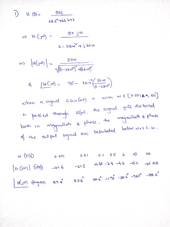
I want the answer for Part B I have the answer for Part A-Q1 I uploaded it

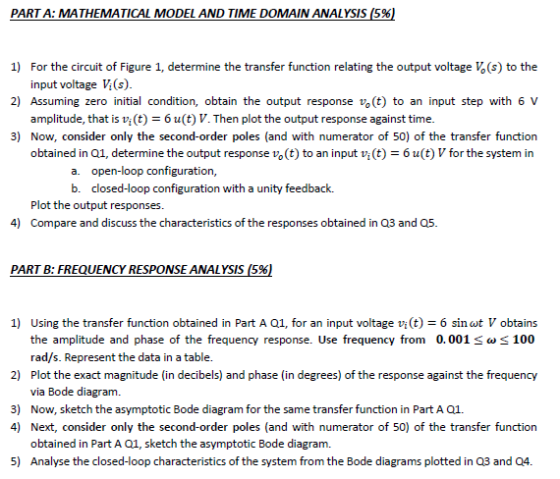

PART A: MATHEMATICAL MODEL AND TIME DOMAIN ANALYSIS (5%) 1) For the circuit of Figure 1, determine the transfer function relating the output voltage (s) to the input voltage V(s). Assuming zero initial condition, obtain the output response vo(t) to an input step with 6V amplitude, that is vi(t)6 u(t) V. Then plot the output response against time. 2) 3) Now, consider only the second-order poles (and with numerator of 50) of the transfer function obtained in Q1, determine the output response vo(t) to an input v(t)6 u(t)Vfor the system in a. open-loop configuration, b. closed-loop configuration with a unity feedback. Plot the output responses. 4) Compare and discuss the characteristics of the responses obtained in Q3 and Q5. PART B: FREQUENCY RESPONSE ANALYSIS (5%) 1) Using the transfer function obtained in Part A 01, for an input voltage vit)6 sin wt V obtains the amplitude and phase of the frequency response. Use frequency from 0.001 100 rad/s. Represent the data in a table. 2) Plot the exact magnitude (in decibels) and phase (in degrees) of the response against the frequency via Bode diagram. 3) Now, sketch the asymptotic Bode diagram for the same transfer function in Part A 01. 4) Next, consider only the second-order poles (and with numerator of 50) of the transfer function obtained in Part A Q1, sketch the asymptotic Bode diagram. 5) Analyse the closed-loop characteristics of the system from the Bode diagrams plotted in Q3 and Q4.
Q1: At loop 1: -V(s) + Ls, (s) + R14(s) + R, (h(s)-4(s)) = 0 (2s 6)1s) (4)12(s) V(s) At loop 2: -0.5(R,(s) 2(s) +Rala(s)+R22(s) R21(s)0 (-5),(s) + ( 14) 4(s) = 0 1ド 2 H 0.5 (2s +6) (-4) MI 6 28s66 -5) 5+14) 4Ω !(2-56) vios, 5V(s) skis (28s +66) 50V (s) (s) = (25s+466) る(s)-1012 (s) => Vo(s) 50 50s (28s +0+66)(28s 665+6)
Homework Answers


Add Answer to:
I want the answer for Part B I have the answer for Part A-Q1 I uploaded it 2 H I F ua 212 < > 0.5% on Y; 4Ω Fig...
I know how to do part a but i really need help with part B. Thanks...
 I know how to do part a but i really need help with part B.
Thanks
1. a) Use MATLAB or Excel to create a Bode plot of the transfer function G(S) +0.5 0.5 s 1.0. for 0.0 1 a) 100 b) Discretize the transfer function using a backwards difference (Euler) transformation. Write a routine in MATLAB or Excel to calculate the output of the transfer function given an input signal. Use your routine to calculate the outputs for the...
I know how to do part a but i really need help with part B.
Thanks
1. a) Use MATLAB or Excel to create a Bode plot of the transfer function G(S) +0.5 0.5 s 1.0. for 0.0 1 a) 100 b) Discretize the transfer function using a backwards difference (Euler) transformation. Write a routine in MATLAB or Excel to calculate the output of the transfer function given an input signal. Use your routine to calculate the outputs for the...
The transfer function of the given physical system is 2500 Gp(s)-T-1000 Part 3 1. Frequency response (a) Draw the bode...
 The transfer function of the given physical system is 2500 Gp(s)-T-1000 Part 3 1. Frequency response (a) Draw the bode plot of open-loop transfer function when K (b) Use bode plot of open-loop transfer function to determine the type of system (do not use transfer function) (c) For what input the system will have constant steady-state error (d) for the unit input in item (c) calculate the constant steady-state error.(Use bode plot to calculate the error.) (e) Design a lead...
etermine the transfer function of the circuit where i^(t) is the output variable and v.ct) is...
 etermine the transfer function of the circuit where i^(t) is the output variable and v.ct) is the input variable. Generate the Bode plot showing the frequency response of the circuit. Only show the asymptotic plot of the terms making the transfer function as 5 H 10 k2 10 H 25 H 62.5 nF U) well as the composite plot for both the magnitude and phase.
4. Draw the magnitude characteristic of the Bode plot of the following transfer function: 10s H...
 4. Draw the magnitude characteristic of the Bode plot of the following transfer function: 10s H (s) =-= (s+1)(s+102 L7n Identify the poles and zeros Sketch the magnitude plot. The y-axis should be in dB. The x-axis should logarithmic, but labeled in rad/sec Use MATLAB to draw the complete Bode plot and check your answer. If the input current is un(t) = 2 cos(20t + 5°), what is the output voltage. Use your MATLAB Bode plot to answer this a)...
Problem 2: (40 pts) Part A: (20pts) A third-order system has an of Y(s)-L[y(t) corresponding to...
 Problem 2: (40 pts) Part A: (20pts) A third-order system has an of Y(s)-L[y(t) corresponding to a unit step input u(t) is known to be input of u(t) and an output of y(t). The forced response portion 1 Ys) (3 +3s2+ 4s +5) = a) Determine the input-output differential equation for the system b) From your result in a), determine the transformed free response Yee (s) corresponding to initial conditions of: y(0)= y(0) = 0 and ý(0)-6 Part B (20pts)...
5. Draw the magnitude characteristic of the Bode plot of the following transfer function: H(s)10(10s +11...
 5. Draw the magnitude characteristic of the Bode plot of the following transfer function: H(s)10(10s +11 (S + 200)2 Identify the poles and zeros Sketch the magnitude plot. The y-axis should be in dB. The x-axis should logarithmic, but labeled in rad/sec e) f) g) Use MATLAB to draw the complete Bode plot and check your answer. h) If the input current is VIN(t)-10 cos(t+35"),what is the output voltage. Use your MATLAB Bode plot to answer this.
Op-Amp Circuit Stability Although op-amps behave as single-pole amplifiers which are "uncondition...
 Op-Amp Circuit Stability Although op-amps behave as single-pole amplifiers which are "unconditionally stable," it's still possible to make unstable amplifiers if you don't know what you're doing. The most famous example of this is the voltage differentiator 1. Consider the following circuit: a. Find the expression for this amplifier's ideal gain Aco (s), assuming the op-amp is ideal (a(s) - o. Hint: It's just an inverting amplifier with z and z2 R (5pts) b. Suppose the gain-setting components have values...
Am (t) → volt) Figure Q1 R = 10, L = H, C = F Q1(a)...
 Am (t) → volt) Figure Q1 R = 10, L = H, C = F Q1(a) [2 marks] The transfer function for the circuit in Figure V.(s)__ LC Vin(5) sz+s+ + Form the corresponding differential equation that governs the behaviour of the system Q1(b) [4 marks] Determine a state-space representation for the circuit in Figure Q1 with the states selected as x;(6) v.) and x2(t) = 1,t). Show that it is equal to the following 408 J18+) y(t) = [1...
Part I: For each problem, there is only one right answer 1. The model of a...
 Part I: For each problem, there is only one right answer 1. The model of a system in the frequency domain is A. the transfer function from the input to the output. B. the differential equation which defines the relation between the input and the output. C. the zero-state response of the system D. None 2. For a system whose input r and output y are related by the differential equation u(0)a30) dr(t) +3r(t) dt dt2 the transfer function from...
0.5 F 20 u(t) v 1H Network for Problem 2 e. Find the s-domain current lab(s),...
 0.5 F 20 u(t) v 1H Network for Problem 2 e. Find the s-domain current lab(s), delivered by the network to the RL load connected between terminals ab. f. Find the Transfer Function H(s) considering that the Input is the network voltage source Vs(s), and that the Output is the current lad() of item , immediately above. & Use H(s) to derive the Impulse Response h(t) of the network h. Write an expression for the Output Current lab() exclusively in...
 I know how to do part a but i really need help with part B.
Thanks
1. a) Use MATLAB or Excel to create a Bode plot of the transfer function G(S) +0.5 0.5 s 1.0. for 0.0 1 a) 100 b) Discretize the transfer function using a backwards difference (Euler) transformation. Write a routine in MATLAB or Excel to calculate the output of the transfer function given an input signal. Use your routine to calculate the outputs for the...
I know how to do part a but i really need help with part B.
Thanks
1. a) Use MATLAB or Excel to create a Bode plot of the transfer function G(S) +0.5 0.5 s 1.0. for 0.0 1 a) 100 b) Discretize the transfer function using a backwards difference (Euler) transformation. Write a routine in MATLAB or Excel to calculate the output of the transfer function given an input signal. Use your routine to calculate the outputs for the...
 The transfer function of the given physical system is 2500 Gp(s)-T-1000 Part 3 1. Frequency response (a) Draw the bode plot of open-loop transfer function when K (b) Use bode plot of open-loop transfer function to determine the type of system (do not use transfer function) (c) For what input the system will have constant steady-state error (d) for the unit input in item (c) calculate the constant steady-state error.(Use bode plot to calculate the error.) (e) Design a lead...
 etermine the transfer function of the circuit where i^(t) is the output variable and v.ct) is the input variable. Generate the Bode plot showing the frequency response of the circuit. Only show the asymptotic plot of the terms making the transfer function as 5 H 10 k2 10 H 25 H 62.5 nF U) well as the composite plot for both the magnitude and phase.
 4. Draw the magnitude characteristic of the Bode plot of the following transfer function: 10s H (s) =-= (s+1)(s+102 L7n Identify the poles and zeros Sketch the magnitude plot. The y-axis should be in dB. The x-axis should logarithmic, but labeled in rad/sec Use MATLAB to draw the complete Bode plot and check your answer. If the input current is un(t) = 2 cos(20t + 5°), what is the output voltage. Use your MATLAB Bode plot to answer this a)...
 Problem 2: (40 pts) Part A: (20pts) A third-order system has an of Y(s)-L[y(t) corresponding to a unit step input u(t) is known to be input of u(t) and an output of y(t). The forced response portion 1 Ys) (3 +3s2+ 4s +5) = a) Determine the input-output differential equation for the system b) From your result in a), determine the transformed free response Yee (s) corresponding to initial conditions of: y(0)= y(0) = 0 and ý(0)-6 Part B (20pts)...
 5. Draw the magnitude characteristic of the Bode plot of the following transfer function: H(s)10(10s +11 (S + 200)2 Identify the poles and zeros Sketch the magnitude plot. The y-axis should be in dB. The x-axis should logarithmic, but labeled in rad/sec e) f) g) Use MATLAB to draw the complete Bode plot and check your answer. h) If the input current is VIN(t)-10 cos(t+35"),what is the output voltage. Use your MATLAB Bode plot to answer this.
 Op-Amp Circuit Stability Although op-amps behave as single-pole amplifiers which are "unconditionally stable," it's still possible to make unstable amplifiers if you don't know what you're doing. The most famous example of this is the voltage differentiator 1. Consider the following circuit: a. Find the expression for this amplifier's ideal gain Aco (s), assuming the op-amp is ideal (a(s) - o. Hint: It's just an inverting amplifier with z and z2 R (5pts) b. Suppose the gain-setting components have values...
 Am (t) → volt) Figure Q1 R = 10, L = H, C = F Q1(a) [2 marks] The transfer function for the circuit in Figure V.(s)__ LC Vin(5) sz+s+ + Form the corresponding differential equation that governs the behaviour of the system Q1(b) [4 marks] Determine a state-space representation for the circuit in Figure Q1 with the states selected as x;(6) v.) and x2(t) = 1,t). Show that it is equal to the following 408 J18+) y(t) = [1...
 Part I: For each problem, there is only one right answer 1. The model of a system in the frequency domain is A. the transfer function from the input to the output. B. the differential equation which defines the relation between the input and the output. C. the zero-state response of the system D. None 2. For a system whose input r and output y are related by the differential equation u(0)a30) dr(t) +3r(t) dt dt2 the transfer function from...
 0.5 F 20 u(t) v 1H Network for Problem 2 e. Find the s-domain current lab(s), delivered by the network to the RL load connected between terminals ab. f. Find the Transfer Function H(s) considering that the Input is the network voltage source Vs(s), and that the Output is the current lad() of item , immediately above. & Use H(s) to derive the Impulse Response h(t) of the network h. Write an expression for the Output Current lab() exclusively in...
Most questions answered within 3 hours.
-
If you titrated 30.0 mL of 0.1 M HCl with 0.1 M NaOH, indicate
the approximate...
asked 15 seconds from now -
NADH passes electrons into the electron transport chain. List
the carriers that would receive the electrons,...
asked 7 minutes ago -
A cylindrical cable with a resistivity of 1.6x10⁻⁸ Ω·m and cross
sectional area of 3x10⁻⁵ m^2...
asked 7 minutes ago -
True or False.
A consumer with convex preferences who is indifferent between
the bundles (5,2) and...
asked 11 minutes ago -
A diamond's index of refraction for red light, 656 nm, is 2.410,
while that for blue...
asked 24 minutes ago -
Compare HPLC, SPE, and GC. Identify the differences, the
advantages, and the weaknesses of each method.
asked 25 minutes ago -
Characteristic x-rays emitted by potassium have a wavelength of
0.374 nm. What is the energy of...
asked 27 minutes ago -
there is a function to create two random numbers between 1 and
25 and a function...
asked 46 minutes ago -
At a certain temperature, the ?pKp for the decomposition of
H2SH2S is 0.832.0.832.
H2S(g)↽−−⇀H2(g)+S(g)H2S(g)↽−−⇀H2(g)+S(g)
Initially, only...
asked 39 minutes ago -
Part 1.C&A Fast Food has four activities in serving a
customer: greet customer, take order, process...
asked 46 minutes ago -
Which attribute allows you to specify a custom "thumbnail" for
multimedia elements?
asked 1 hour ago -
How much 0.1200 M sodium hydroxide solution is need to titrate
14 mL of a 0.100...
asked 1 hour ago