
Homework Answers


resistance value is the approximate value.
Add Answer to:
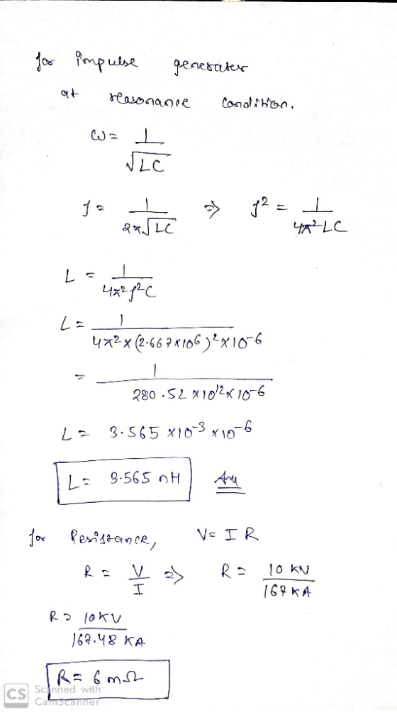
25-An impulse generator has a capacitance of 1 μF rated to 10 kV and uses series RL circuit to produce 1,5/40 us vol...
A series RLC circuit has a capacitor with a capacitance of 36.0 μF , an inductor...
A series RLC circuit has a capacitor with a capacitance of 36.0 μF , an inductor with an inductance of 0.700 H and a resistor with a resistance of 143 Ω. The circuit is attached to a source that has a rms voltage of 65.0 V and a frequency of 91.0 Hz. What is the peak current?
A series RLC circuit that has an inductance of 6 mH, a capacitance of 3 μF,...
 A series RLC circuit that has an inductance of 6 mH, a capacitance of 3 μF, and a resistance of 7.2 is driven by an ideal ac voltage source that has a peak emf of 110 V (a) Find the resonant frequency 1.19 rad/s (b) Find the root-means-square current at resonance When the frequency is 8000 rad/s, find the following values. (c) the capacitive and inductive reactances (d) the impedance (e) the root-mean square current. (f) the phase angle δ...
Function Generatr Inductor Model Ra R, Figure 1 Series RLC Circuit Preliminary This laboratory wi...
 Function Generatr Inductor Model Ra R, Figure 1 Series RLC Circuit Preliminary This laboratory will demonstrate how varying resistance changes the natural response of a series RLC circuit (Fig. 1). The function generator is modeled as an ideal voltage source v(t) 5 u() V in series with source resistance Rs-50Q. After measurements using an LCR meter, the inductor is modeled as an ideal L 90 mH inductor in series with resistance RL-20Q. The capacitance is C-0.22 μF. 1) Calculate the...
(a) A capacitor of capacitance 220 μF is connected in series with a 150 kΩ resistor, a switch and an ammeter. A d.c. power supply of negligible internal resistance is connected to the circuit as show...
 (a) A capacitor of capacitance 220 μF is connected in series with a 150 kΩ resistor, a switch and an ammeter. A d.c. power supply of negligible internal resistance is connected to the circuit as shown below 1 50 kΩ 220HF A stopclock is started and after 10 seconds the switch S is closed Ammeter readings are noted at regular intervals until a time of 80s is shown on the stopclock. The graph below shows how the current in the...
32. A transformer is to be designed to increase the 30 kV-rms output of a generator...
 32. A transformer is to be designed to increase the 30 kV-rms output of a generator to the transmission-line voltage of 345 kV-om. If the primary winding has 80 turns, how many turns must the secondary have? b. 70 c. 920 d. 9200 e 12 33. The primary winding of an electric train transformer has 400 turns and the Secondary has 50. If the input voltage is 120V(rms) what is the output voltage? a. 15 V (rms) b. 30 Vrms)...
EXPERIMENT 11 STEP RESPONSE TO RC AND RL CIRCUITS pages 11-4 thru 11-7. tep response of the RC an...
 EXPERIMENT 11 STEP RESPONSE TO RC AND RL CIRCUITS pages 11-4 thru 11-7. tep response of the RC and RL circuits is included in OBJECTIVE: O analyze the voltage and current characteristics of a Resistance - Capacitance (RC) circuit when driven by a step voltage function. To analyze the voltage and current characteristics of a Resistance- Inductor (RL) circuit when driven by a step voltage function To design an RC circuit to yield a specified output voltage with a step...
(2 points) Two driven inductors A R = 1 kΩ resistor, a L1 = 20 mH...
 (2 points) Two driven inductors A R = 1 kΩ resistor, a L1 = 20 mH inductor and a L2 28 mH inductor are connected in series. A funtion generator drives the circuit with a 5 Vpp variable frequency sine wave. (a) What is the equivalent impedance Zeq of this circuit? O A. R +jwLIL2/(L1+ L2) E. None of these (b) For what angular frequency does |Zoq v2 R? 20833.3 radians/sec (c) What is the peak-to-peak value of the voltage...
Submission should follow the ET190 homework format. Ensure you show all work completety to receive full...
 Submission should follow the ET190 homework format. Ensure you show all work completety to receive full credit. Make sure all problems are done in using labels and appropriate units or subscripts. Box your final answer. 1. There are 5 capacitors with the value of 1500 pF. a. What is the total capacitance when they are all in series? -10 3e 1500 1500 1500 b. What is the total capacitance when they are all in parallel? Cr cie C Cs de...
Course and Section cto EXPERIMENT ac series-Parallel Sinusoidal Circuits OBJECTIVES 1. Measure th...
 Course and Section cto EXPERIMENT ac series-Parallel Sinusoidal Circuits OBJECTIVES 1. Measure the currents of series-parallel R-L and R-C networks using sensing resistors 2. Demonstrate the Pythagorean relationship between the currents of the networks. 3. Measure the phase angles associated with the currents of the networks. 4. Calculate the input impedance of a parallel network using measured values EQUIPMENT REQUIRED Instruments Resistors 1-10-Q, 470-Ω, l-kM (14.W) Inductors 1-10-mH Capacitors 1-0.02-pF I-DMM 1--Oscilloscope 1-Audio oscillator or function generator 1--Frequency counter (if...
O bructe CONFIDENTIAL 2 limitatio of Flyb Q2 (a) With the aid of respective topology, point...
 O bructe CONFIDENTIAL 2 limitatio of Flyb Q2 (a) With the aid of respective topology, point out three (3) basic de-de converters ( 3 marks) (b) Discuss the energy transfer in on each circuit by refering the circuits drawn in Q2(a) (3 marks) (c) Design a boost converter for continuous inductor current and an output nipple voltage of less than 1% that will have an output of 30 V from a 12 V source, Assume the load resistance of 50...
 A series RLC circuit that has an inductance of 6 mH, a capacitance of 3 μF, and a resistance of 7.2 is driven by an ideal ac voltage source that has a peak emf of 110 V (a) Find the resonant frequency 1.19 rad/s (b) Find the root-means-square current at resonance When the frequency is 8000 rad/s, find the following values. (c) the capacitive and inductive reactances (d) the impedance (e) the root-mean square current. (f) the phase angle δ...
 Function Generatr Inductor Model Ra R, Figure 1 Series RLC Circuit Preliminary This laboratory will demonstrate how varying resistance changes the natural response of a series RLC circuit (Fig. 1). The function generator is modeled as an ideal voltage source v(t) 5 u() V in series with source resistance Rs-50Q. After measurements using an LCR meter, the inductor is modeled as an ideal L 90 mH inductor in series with resistance RL-20Q. The capacitance is C-0.22 μF. 1) Calculate the...
 (a) A capacitor of capacitance 220 μF is connected in series with a 150 kΩ resistor, a switch and an ammeter. A d.c. power supply of negligible internal resistance is connected to the circuit as shown below 1 50 kΩ 220HF A stopclock is started and after 10 seconds the switch S is closed Ammeter readings are noted at regular intervals until a time of 80s is shown on the stopclock. The graph below shows how the current in the...
 32. A transformer is to be designed to increase the 30 kV-rms output of a generator to the transmission-line voltage of 345 kV-om. If the primary winding has 80 turns, how many turns must the secondary have? b. 70 c. 920 d. 9200 e 12 33. The primary winding of an electric train transformer has 400 turns and the Secondary has 50. If the input voltage is 120V(rms) what is the output voltage? a. 15 V (rms) b. 30 Vrms)...
 EXPERIMENT 11 STEP RESPONSE TO RC AND RL CIRCUITS pages 11-4 thru 11-7. tep response of the RC and RL circuits is included in OBJECTIVE: O analyze the voltage and current characteristics of a Resistance - Capacitance (RC) circuit when driven by a step voltage function. To analyze the voltage and current characteristics of a Resistance- Inductor (RL) circuit when driven by a step voltage function To design an RC circuit to yield a specified output voltage with a step...
 (2 points) Two driven inductors A R = 1 kΩ resistor, a L1 = 20 mH inductor and a L2 28 mH inductor are connected in series. A funtion generator drives the circuit with a 5 Vpp variable frequency sine wave. (a) What is the equivalent impedance Zeq of this circuit? O A. R +jwLIL2/(L1+ L2) E. None of these (b) For what angular frequency does |Zoq v2 R? 20833.3 radians/sec (c) What is the peak-to-peak value of the voltage...
 Submission should follow the ET190 homework format. Ensure you show all work completety to receive full credit. Make sure all problems are done in using labels and appropriate units or subscripts. Box your final answer. 1. There are 5 capacitors with the value of 1500 pF. a. What is the total capacitance when they are all in series? -10 3e 1500 1500 1500 b. What is the total capacitance when they are all in parallel? Cr cie C Cs de...
 Course and Section cto EXPERIMENT ac series-Parallel Sinusoidal Circuits OBJECTIVES 1. Measure the currents of series-parallel R-L and R-C networks using sensing resistors 2. Demonstrate the Pythagorean relationship between the currents of the networks. 3. Measure the phase angles associated with the currents of the networks. 4. Calculate the input impedance of a parallel network using measured values EQUIPMENT REQUIRED Instruments Resistors 1-10-Q, 470-Ω, l-kM (14.W) Inductors 1-10-mH Capacitors 1-0.02-pF I-DMM 1--Oscilloscope 1-Audio oscillator or function generator 1--Frequency counter (if...
 O bructe CONFIDENTIAL 2 limitatio of Flyb Q2 (a) With the aid of respective topology, point out three (3) basic de-de converters ( 3 marks) (b) Discuss the energy transfer in on each circuit by refering the circuits drawn in Q2(a) (3 marks) (c) Design a boost converter for continuous inductor current and an output nipple voltage of less than 1% that will have an output of 30 V from a 12 V source, Assume the load resistance of 50...
Most questions answered within 3 hours.
-
Write a program to solve the Josephus problem, with the following
modification:
Sample Input:
./a.out n...
asked 48 minutes ago -
At the start of a CD it is spinning at a rate of 525 rpm
(revolutions...
asked 1 hour ago -
4. Without doing any calculations, predict whether the observed
∆T would increase, decrease or remain the...
asked 2 hours ago -
Based on the range, which of the following sets of scores has
the greatest variability? 3,...
asked 3 hours ago -
Ripples in a pond travel at a velocity of 3 m/s with one peak
passing a...
asked 3 hours ago -
A man stands on the roof of a building of height 13.0 mm and
throws a...
asked 3 hours ago -
The extent to which assets are financed by borrowed funds and
other liabilities is indicated by:...
asked 4 hours ago -
Explain in detail
Germany is the fifth largest economy
explain what goods and services Germany specializes...
asked 4 hours ago -
The density of platinum is 21.45 g/mL. If a cube of platinum
with a mass of...
asked 5 hours ago -
Accounts Receivable
Sales
A/R Posting
Extended Sales Invoice
Packing Slip
Compare invoice to packing slip 2...
asked 5 hours ago -
Michaella, age 23, is a full-time law student and is claimed by
her parents as a...
asked 5 hours ago -
Why are polymers not typically casted into products?
asked 5 hours ago