0 0 0 0 2 0 0 5 0 5 5 00000000001 28642
Homework Answers

Add Answer to:
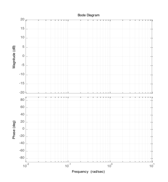
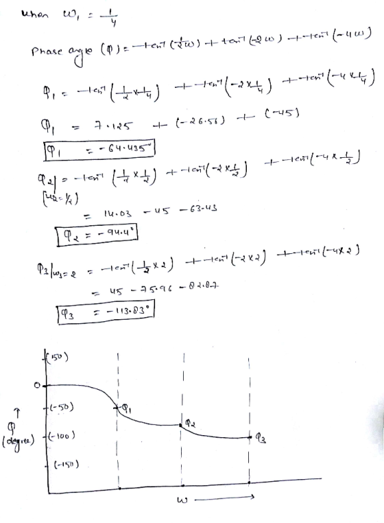
2. Given the following transfer function S+ 2 Sketch the Bode plots, by marking the breakpoint frequencies, asymptotes...
Sketch the bode plot of a signal conditioner with the transfer function G(s) in the provided...
 Sketch the bode plot of a signal conditioner with the transfer function G(s) in the provided graph and calculate the bandwidth of this signal conditioner. GO 10s +1 S2 + 10s + 24 Table 2 Components in G(S) Asymptotes for Magnitude Asymptotes for Phase 20 log,0 1G(jw) Frequency-rad/sec Phase - degrees Frequency - rad/sec
For the following transfer function, sketch approximate straight-line Bode plots, including magnitude and phase plots. Show...
 For the following transfer function, sketch approximate
straight-line Bode plots, including magnitude and phase plots. Show
all steps clearly
10 4 (A)G(s)-7 s (s 2s +100)
For the following transfer function, sketch approximate
straight-line Bode plots, including magnitude and phase plots. Show
all steps clearly
10 4 (A)G(s)-7 s (s 2s +100)
Sketch the Bode magnitude and phase plots for the following transfer function: G(s)=- a fimction: G(9)=...
 Sketch the Bode magnitude and phase plots for the following transfer function: G(s)=- a fimction: G(9)= (s+2016+4) (s + 2)(+4)
For all problems -given a transfer function G(s) sketch the magnitude and phase characteristics in the...
 For all problems -given a transfer function G(s) sketch the magnitude and phase characteristics in the logarithmic scale (i.e. Bode-plots) of the system using the following rules-of-thumb: i. "Normalize" the G(s) by extracting poles/zeros, substituting s-jw and writing the TF using DC-gain KO and time-constants i. Arange break-points (poles, zeros or on for complex-conjugate poles) in ascending order ii Based on the term Ko(ju)Fk, determine: initial slope of the magnitude-response asymptote for low frequencies as F k 20 dB/dec (e.g....
For the given transfer function: Ho-2where s 5 (s s (s +10) where s =j w...
 For the given transfer function: Ho-2where s 5 (s s (s +10) where s =j w Sketch the approximate Bode plots (amplitude and phase). Label all the amplitude values in db, phase values in degrees, the slopes in db/dec, and the corner frequencies in rad/sec.. a. b. If the gain of the transfer function given above, H(s), increased by a factor of 10 (from 5 to 50), what will happen to the approximate Bode plots (amplitude and phase) that you...
QUESTION 2 Consider this 2" order transfer function which was discussed in lecture G(s) 10s+9 The Bode plots (magnitude, phase) for this G(s) are provided in this handout. For the following...
 QUESTION 2 Consider this 2" order transfer function which was discussed in lecture G(s) 10s+9 The Bode plots (magnitude, phase) for this G(s) are provided in this handout. For the following frequency (i.e."o") values, do complex number calculations as performed in lecture, to verify that this magnitude curve (in decibels) and phase curve (in degrees) are correct “o',-0.03, 0.2, 1, 6, 20, and 60 rad/sec Be sure to show your work CLEARLY, and indicate on the Bode plots the magnitude/phase...
1- For each transfer function below, sketch the Bode magnitude and phase plots, a) T(s) 3040S...
 1- For each transfer function below, sketch the Bode magnitude and phase plots, a) T(s) 3040S b) T(S) 30-405
i) Draw the Bode plots (hand sketch, magnitude and phase!) for the following transfer function. Plot...
 i) Draw the Bode plots (hand sketch, magnitude and phase!) for the following transfer function. Plot over the range 0.1 to 1000 rad/s HS 10,000 (s) = s* + 20s 10,000 ii) what are the Q and Bw for this circuit? iii) Design and draw a circuit (including values) that would yield this transfer function. It should use a 100mH inductor , , Qano
1. (a) sketch the Bode magnitude and phase plots of a transfer function T(W) = Vo(w)...
 1. (a) sketch the Bode magnitude and phase plots of a transfer function T(W) = Vo(w) given Wo = 27x1oʻrad/s. Vi (w) (l+ges/wo2 g (6) Calculate the half-power or 3-dB Cut-off frequency of the above transfer function, and the phase LT(W) at the 3-dB cut-off frequency.
Bode Plots Sketch the Bode plot magnitude and phase for each of the three open-loop transfer...
Bode Plots Sketch the Bode plot magnitude and phase for each of the three open-loop transfer functions listed below. Verify your results using the bode m function in MATLAB.(a) \(G(s)=\frac{100}{s(0.1 s+1)(0.01 s+1)}\)(b) \(G(s)=\frac{1}{(s+1)^{2}\left(s^{2}+s+9\right)}\)(c) \(G(s)=\frac{16000 s}{(s+1)(s+100)\left(s^{2}+5 s+1600\right)}\)
 Sketch the bode plot of a signal conditioner with the transfer function G(s) in the provided graph and calculate the bandwidth of this signal conditioner. GO 10s +1 S2 + 10s + 24 Table 2 Components in G(S) Asymptotes for Magnitude Asymptotes for Phase 20 log,0 1G(jw) Frequency-rad/sec Phase - degrees Frequency - rad/sec
 For the following transfer function, sketch approximate
straight-line Bode plots, including magnitude and phase plots. Show
all steps clearly
10 4 (A)G(s)-7 s (s 2s +100)
For the following transfer function, sketch approximate
straight-line Bode plots, including magnitude and phase plots. Show
all steps clearly
10 4 (A)G(s)-7 s (s 2s +100)
 Sketch the Bode magnitude and phase plots for the following transfer function: G(s)=- a fimction: G(9)= (s+2016+4) (s + 2)(+4)
 For all problems -given a transfer function G(s) sketch the magnitude and phase characteristics in the logarithmic scale (i.e. Bode-plots) of the system using the following rules-of-thumb: i. "Normalize" the G(s) by extracting poles/zeros, substituting s-jw and writing the TF using DC-gain KO and time-constants i. Arange break-points (poles, zeros or on for complex-conjugate poles) in ascending order ii Based on the term Ko(ju)Fk, determine: initial slope of the magnitude-response asymptote for low frequencies as F k 20 dB/dec (e.g....
 For the given transfer function: Ho-2where s 5 (s s (s +10) where s =j w Sketch the approximate Bode plots (amplitude and phase). Label all the amplitude values in db, phase values in degrees, the slopes in db/dec, and the corner frequencies in rad/sec.. a. b. If the gain of the transfer function given above, H(s), increased by a factor of 10 (from 5 to 50), what will happen to the approximate Bode plots (amplitude and phase) that you...
 QUESTION 2 Consider this 2" order transfer function which was discussed in lecture G(s) 10s+9 The Bode plots (magnitude, phase) for this G(s) are provided in this handout. For the following frequency (i.e."o") values, do complex number calculations as performed in lecture, to verify that this magnitude curve (in decibels) and phase curve (in degrees) are correct “o',-0.03, 0.2, 1, 6, 20, and 60 rad/sec Be sure to show your work CLEARLY, and indicate on the Bode plots the magnitude/phase...
 1- For each transfer function below, sketch the Bode magnitude and phase plots, a) T(s) 3040S b) T(S) 30-405
 i) Draw the Bode plots (hand sketch, magnitude and phase!) for the following transfer function. Plot over the range 0.1 to 1000 rad/s HS 10,000 (s) = s* + 20s 10,000 ii) what are the Q and Bw for this circuit? iii) Design and draw a circuit (including values) that would yield this transfer function. It should use a 100mH inductor , , Qano
 1. (a) sketch the Bode magnitude and phase plots of a transfer function T(W) = Vo(w) given Wo = 27x1oʻrad/s. Vi (w) (l+ges/wo2 g (6) Calculate the half-power or 3-dB Cut-off frequency of the above transfer function, and the phase LT(W) at the 3-dB cut-off frequency.
Most questions answered within 3 hours.
-
3. Gains from trade
Consider two neighbouring island countries called Euphoria and
Contente. They each have...
asked 35 minutes ago -
A business executive has the option to invest money in two
plans: Plan A guarantees that...
asked 2 hours ago -
Hello, can someone please help me answer this question?
How much heat is absorbed by a...
asked 2 hours ago -
. A marketing researcher conducted a survey of 25 shoppers
randomly selected at the local mall...
asked 3 hours ago -
Create an comprehensive response to the
following:
Antimicrobial agents work on a multitude of microbes (bacteria,...
asked 3 hours ago -
6.13 LAB: Step counter. Section 6.3.
A pedometer treats walking 2,000 steps as walking 1 mile....
asked 3 hours ago -
(14.2) A block of mass m = 10 kg riding on a frictionless
horizontal plane is...
asked 3 hours ago -
Use any search engine to search for articles about Starbucks
partnership with Tata Companies in India...
asked 3 hours ago -
Let’s say that for some reason Bank Excess Reserves suddenly
increase sharply. What effect would this...
asked 3 hours ago -
Given:
Curent Assets: $600,000
Total Assets: $2,600,000
Current Liabilities: $500,000
Total Liabilities: $1,700,000
What is the...
asked 3 hours ago -
1. What is a “Bankster”? What is insider trading? Why is it
illegal?
2. What is...
asked 3 hours ago -
A transverse wave on a cord is given by
D(x,t)=0.18sin(2.7x−61.0t), where Dand x are in m...
asked 3 hours ago