solve using kinetic energy equations. ( Theorem of change in kinetic enegery)

Homework Answers


Add Answer to:
solve using kinetic energy equations. ( Theorem of change in kinetic enegery) KE20. Figure shows a mechanism. Body 5...
Please help me to solve this. KE13. Figure shows a mechanism. Body 5 is assumed to be homogeneous circular cylinder, and mass of the pulley 4 is uniformly distributed over its rim. The coefficient...
 Please help me to solve this.
KE13. Figure shows a mechanism. Body 5 is assumed to be homogeneous circular cylinder, and mass of the pulley 4 is uniformly distributed over its rim. The coefficient of sliding friction between bodies and the plane is f 0.1. The coefficient of stiffness of a spring is c. A force F applied to the mechanism depends on the displacement si of the body 1. The mechanism starts motion from rest, and at the beginning...
Please help me to solve this.
KE13. Figure shows a mechanism. Body 5 is assumed to be homogeneous circular cylinder, and mass of the pulley 4 is uniformly distributed over its rim. The coefficient of sliding friction between bodies and the plane is f 0.1. The coefficient of stiffness of a spring is c. A force F applied to the mechanism depends on the displacement si of the body 1. The mechanism starts motion from rest, and at the beginning...
KE7. Figure shows a mechanism. Body 5 is assumed to be homogeneous circular cylinder, and mass of the pulley 4 is uniformly distributed over its rim. The coefficient of sliding friction between bo...
 KE7. Figure shows a mechanism. Body 5 is assumed to be homogeneous circular cylinder, and mass of the pulley 4 is uniformly distributed over its rim. The coefficient of sliding friction between bodies and the plane is f 0.1. The coefficient of stiffness of a spring is c. A force F applied to the mechanism depends on the displacement s of the body 1. The mechanism starts motion from rest, and F at the beginning of the motion the spring...
Find the angular velocity w3 at instant s1=0.2m KEl6. Figure shows a mechanism. Body 5 is assumed to be homogeneous circular cylinder, and mass of the pulley 4 is uniformly distributed over its ri...
 Find the angular velocity w3 at instant s1=0.2m
KEl6. Figure shows a mechanism. Body 5 is assumed to be homogeneous circular cylinder, and mass of the pulley 4 is uniformly distributed over its rim. The coefficient of sliding friction between bodies and the plane is f 0.1. The coefficient of stiffness of a spring is e. A force Fapplied to the mechanism depends on the displacement si of the body 1. The mechanism starts motion from rest, and at the...
Find the angular velocity w3 at instant s1=0.2m
KEl6. Figure shows a mechanism. Body 5 is assumed to be homogeneous circular cylinder, and mass of the pulley 4 is uniformly distributed over its rim. The coefficient of sliding friction between bodies and the plane is f 0.1. The coefficient of stiffness of a spring is e. A force Fapplied to the mechanism depends on the displacement si of the body 1. The mechanism starts motion from rest, and at the...
1 m Mm F Sl. In the mechanism shown the circular body with the mass moment...
 1 m Mm F Sl. In the mechanism shown the circular body with the mass moment of inertia I about 0. i.e. the center of gravity of the body, rotates about O. The T shaped body with the mass m is attached to that circular k body through the joint A such that OA = r. and it translates along the horizontal direction. The linear spring with stiffness k is placed between the T shaped body and the ground such...
QUESTION 2 |15 MARKSI (a) Figure 2 shows a collar with a mass, m of 25...
 QUESTION 2 |15 MARKSI (a) Figure 2 shows a collar with a mass, m of 25 kg and coefficient of kinetic friction, pk of 0.3. The attached spring has an unstretched length 7=0.15 m and a stiffness k = 55 Nm. (i) Draw the free-body diagram (FBD) of the system when the collar is at point A with applied force, F = 250 N acting at angle 6 = 30° as shown in Figure 2. [4 Marks] (ii) Find the...
Can someone solve these? ill award a thumbs up Force Balance and Free body Diagrams 9....
 Can someone solve these? ill award a thumbs up
Force Balance and Free body Diagrams 9. (2) True or false: Dynamic equilibrium involves a net force equal to zero and the object at rest 10. (2) True or false: A hockey puck sliding on a frictionless Ice rink at constant velocity is in dynamic equilibrium. 11. (2) True or False: A stoplight hanging motionless from a wire is in dynamic equilibrium For questions 12, 13 and 14 draw and label...
Can someone solve these? ill award a thumbs up
Force Balance and Free body Diagrams 9. (2) True or false: Dynamic equilibrium involves a net force equal to zero and the object at rest 10. (2) True or false: A hockey puck sliding on a frictionless Ice rink at constant velocity is in dynamic equilibrium. 11. (2) True or False: A stoplight hanging motionless from a wire is in dynamic equilibrium For questions 12, 13 and 14 draw and label...
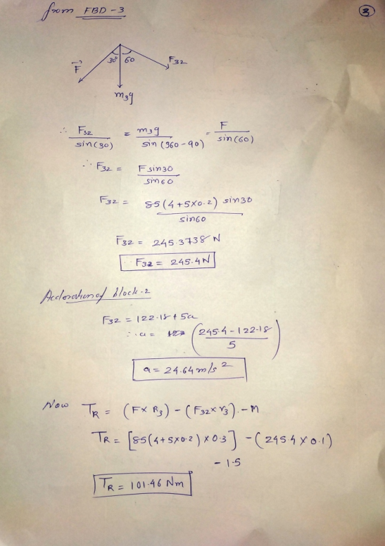
Problem 3: For the mechanism system as shown in Figure 3. The block A is moving down 0,3 m/s in initial condition. B...
 Problem 3: For the mechanism system as shown in Figure 3. The block A is moving down 0,3 m/s in initial condition. Block A has mass of mA 75 kg. The cylinder B is considered a homogeneous solid and moves in frictionless bearings. The mass of cylinder B is m 85 kg and its radius is r 150 mm. Block C has mass of mc 145 kg. The kinetic coefficient of friction between block C and the mc 145 kg...
(15 points) (45 minutes) he figure below shows a slider crank mechanism with an external force...
 (15 points) (45 minutes) he figure below shows a slider crank mechanism with an external force applied to the piston. For the given crank velocity at the shown configuration, find the following: 1 Draw free body diagram for each link showing the coordinate frames, accelerations, reaction forces, and externally applied forces. Points) 2. Apply Newton's law to develop the dynamic equations of motion for each link. 3. Solve for all the reaction forces and the crank torque (S (5 Points)...
Question B A machine on a viscoelastic foundation (Figure 31.1), modelled as a spring mass-damper system...
 Question B A machine on a viscoelastic foundation (Figure 31.1), modelled as a spring mass-damper system is acted upon by a force modelled as a harmonic force: F(t) = 0.2 sin(wt) Force is given in N and time in seconds. W Figure 31.1 Nos Given numerical values: m = 10 kg C=5 M k = 1000 = 1) draw the correct Free-Body-Diagram and determine the equation of motion [2 marks) 2) determine the natural frequency and the damping ratio of...
For the system shown in Fig. 1, solve the following problems. (a) Find the transfer function, G(s...
 For the system shown in Fig. 1, solve the following problems. (a) Find the transfer function, G(s)X2 (s)/F(s) (b) Does the system oscillate with a unit step input (f (t))? Explain the reason (c) Decide if the system(x2 (t)) is stable with a unit step input (f (t))? Explain the reason 1. 320) 8 kg 2 N/m 4N-s/m 2N-s/m Fig. 1 2. There are two suspensions for a car as shown in Fig. 2 (a) Find the equations of each...
 Please help me to solve this.
KE13. Figure shows a mechanism. Body 5 is assumed to be homogeneous circular cylinder, and mass of the pulley 4 is uniformly distributed over its rim. The coefficient of sliding friction between bodies and the plane is f 0.1. The coefficient of stiffness of a spring is c. A force F applied to the mechanism depends on the displacement si of the body 1. The mechanism starts motion from rest, and at the beginning...
Please help me to solve this.
KE13. Figure shows a mechanism. Body 5 is assumed to be homogeneous circular cylinder, and mass of the pulley 4 is uniformly distributed over its rim. The coefficient of sliding friction between bodies and the plane is f 0.1. The coefficient of stiffness of a spring is c. A force F applied to the mechanism depends on the displacement si of the body 1. The mechanism starts motion from rest, and at the beginning...
 KE7. Figure shows a mechanism. Body 5 is assumed to be homogeneous circular cylinder, and mass of the pulley 4 is uniformly distributed over its rim. The coefficient of sliding friction between bodies and the plane is f 0.1. The coefficient of stiffness of a spring is c. A force F applied to the mechanism depends on the displacement s of the body 1. The mechanism starts motion from rest, and F at the beginning of the motion the spring...
 Find the angular velocity w3 at instant s1=0.2m
KEl6. Figure shows a mechanism. Body 5 is assumed to be homogeneous circular cylinder, and mass of the pulley 4 is uniformly distributed over its rim. The coefficient of sliding friction between bodies and the plane is f 0.1. The coefficient of stiffness of a spring is e. A force Fapplied to the mechanism depends on the displacement si of the body 1. The mechanism starts motion from rest, and at the...
Find the angular velocity w3 at instant s1=0.2m
KEl6. Figure shows a mechanism. Body 5 is assumed to be homogeneous circular cylinder, and mass of the pulley 4 is uniformly distributed over its rim. The coefficient of sliding friction between bodies and the plane is f 0.1. The coefficient of stiffness of a spring is e. A force Fapplied to the mechanism depends on the displacement si of the body 1. The mechanism starts motion from rest, and at the...
 1 m Mm F Sl. In the mechanism shown the circular body with the mass moment of inertia I about 0. i.e. the center of gravity of the body, rotates about O. The T shaped body with the mass m is attached to that circular k body through the joint A such that OA = r. and it translates along the horizontal direction. The linear spring with stiffness k is placed between the T shaped body and the ground such...
 QUESTION 2 |15 MARKSI (a) Figure 2 shows a collar with a mass, m of 25 kg and coefficient of kinetic friction, pk of 0.3. The attached spring has an unstretched length 7=0.15 m and a stiffness k = 55 Nm. (i) Draw the free-body diagram (FBD) of the system when the collar is at point A with applied force, F = 250 N acting at angle 6 = 30° as shown in Figure 2. [4 Marks] (ii) Find the...
 Can someone solve these? ill award a thumbs up
Force Balance and Free body Diagrams 9. (2) True or false: Dynamic equilibrium involves a net force equal to zero and the object at rest 10. (2) True or false: A hockey puck sliding on a frictionless Ice rink at constant velocity is in dynamic equilibrium. 11. (2) True or False: A stoplight hanging motionless from a wire is in dynamic equilibrium For questions 12, 13 and 14 draw and label...
Can someone solve these? ill award a thumbs up
Force Balance and Free body Diagrams 9. (2) True or false: Dynamic equilibrium involves a net force equal to zero and the object at rest 10. (2) True or false: A hockey puck sliding on a frictionless Ice rink at constant velocity is in dynamic equilibrium. 11. (2) True or False: A stoplight hanging motionless from a wire is in dynamic equilibrium For questions 12, 13 and 14 draw and label...
 Problem 3: For the mechanism system as shown in Figure 3. The block A is moving down 0,3 m/s in initial condition. Block A has mass of mA 75 kg. The cylinder B is considered a homogeneous solid and moves in frictionless bearings. The mass of cylinder B is m 85 kg and its radius is r 150 mm. Block C has mass of mc 145 kg. The kinetic coefficient of friction between block C and the mc 145 kg...
 (15 points) (45 minutes) he figure below shows a slider crank mechanism with an external force applied to the piston. For the given crank velocity at the shown configuration, find the following: 1 Draw free body diagram for each link showing the coordinate frames, accelerations, reaction forces, and externally applied forces. Points) 2. Apply Newton's law to develop the dynamic equations of motion for each link. 3. Solve for all the reaction forces and the crank torque (S (5 Points)...
 Question B A machine on a viscoelastic foundation (Figure 31.1), modelled as a spring mass-damper system is acted upon by a force modelled as a harmonic force: F(t) = 0.2 sin(wt) Force is given in N and time in seconds. W Figure 31.1 Nos Given numerical values: m = 10 kg C=5 M k = 1000 = 1) draw the correct Free-Body-Diagram and determine the equation of motion [2 marks) 2) determine the natural frequency and the damping ratio of...
 For the system shown in Fig. 1, solve the following problems. (a) Find the transfer function, G(s)X2 (s)/F(s) (b) Does the system oscillate with a unit step input (f (t))? Explain the reason (c) Decide if the system(x2 (t)) is stable with a unit step input (f (t))? Explain the reason 1. 320) 8 kg 2 N/m 4N-s/m 2N-s/m Fig. 1 2. There are two suspensions for a car as shown in Fig. 2 (a) Find the equations of each...
Most questions answered within 3 hours.
-
Convert the high level language programming statementts to 80x86
assembly, Assume X=AX and y=BX
for (i=1;...
asked 1 minute ago -
SoleMate’s Burkins sneakers cost $40 per pair from the supplier
and are sold by SoleMate at...
asked 5 minutes ago -
The movie Moneyball (based on the book by Michael
Lewis) tells the story of Billy Beane,...
asked 4 minutes ago -
A regional highway uses 8 tollbooths that are open to all
vehicles. A chi-square goodness-of-fit test...
asked 7 minutes ago -
In her Semiannual Monetary Policy Report to Congress on July 13,
2017, then Federal Reserve Chair...
asked 7 minutes ago -
Suppose N packets are sent,
and each packet arrives at rate of L/2R to a link....
asked 26 minutes ago -
17. Show the steps involved in reduction of the ketone in fatty
acid synthesis. Which cofactor...
asked 27 minutes ago -
5.61 g of octane, C8H18, reacts with excess oxygen in a bomb
calorimeter. The heat capacity...
asked 31 minutes ago -
The velocity field of a flow is given by V = (2+1) x
y2 i +...
asked 40 minutes ago -
(EPS with
Convertible Bonds) On June 1, 2012, Bluhm Company and
Amanar Company merged to form...
asked 38 minutes ago -
2. Discuss why the study exemplifies one that agrees with The
American Psychological Association’s (APA) Ethical...
asked 42 minutes ago -
Without considering the following capital gains and losses,
Charlene, who is single, has a taxable income...
asked 49 minutes ago