
D2 01 D1 Vsw V swi Vs 0 Figure 2.2 Non-inverting Buck-Boost during inductor charging period (D × T). D2 01 D1 Vswzq2 Vo Vs SW1 Figure 2.3 Non-inverting Buck-Boost during inductor dis-charging period (Di T). D2 01 DCM+ SW2 02 Figure 2.4 Non-inverting Buck-Boost during discontinuous conduction period (1-D-D) × T).
Homework Answers

Add Answer to:
Please, need help to do this. the mode is DCM mode. Problem 2.1 Sketch the current and voltage waveforms of: the in...
Problem 2.2 Using the same methods shown in lecture, mathematically derive: (a) The voltage conversion ratio equat...
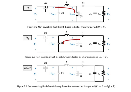
 Problem 2.2 Using the same methods shown in lecture, mathematically derive: (a) The voltage conversion ratio equationwhen the Buck-Boost is operating in Discontinuous Conduction Mode (DCM). Your answer should be a function of D, Ro, T, and L (b) The value of the inductor discharge duty cycle coefficient; D1.Your answer should be a function of Ro, T, and L. Hint 1: Other than assessing the current waveforms, you will also need to apply the assumption of 100% efficiency from Problem...
Problem 2.2 Using the same methods shown in lecture, mathematically derive: (a) The voltage conversion ratio...
 Problem 2.2 Using the same methods shown in lecture, mathematically derive: (a) The voltage conversion ratio equationwhen the Buck-Boost is operating in Discontinuous Conduction Mode (DCM). Your answer should be a function of D, Ro, T, and L (b) The value of the inductor discharge duty cycle coefficient; D1.Your answer should be a function of Ro, T, and L. Hint 1: Other than assessing the current waveforms, you will also need to apply the assumption of 100% efficiency from Problem...
Problem 2.3 By considering all the diodes in Figure 2.5, which of the following statements are true for a non-inve...
 Problem 2.3 By considering all the diodes in Figure 2.5, which of the following statements are true for a non-inverting Buck-Boost converter? (clearly indicate TRUE or FALSE for each statement) The magnitude/Peak-to-Peak Voltage of the switch node oscillations must be: (a) Greater than Vs (b) Greater than Vo (c) Less than both Vo AND Vs Assume VOV for all four diodes. C. V swz V swi D2 CGD 01 Ci 0 0 Vs Ci 02 Figure 2.5 Schematic of Non-inverting...
Q4. (a) Fig. Q4(a) shows a buck-boost converter. Sketch waveforms for the choke current when in b...
 Q4. (a) Fig. Q4(a) shows a buck-boost converter. Sketch waveforms for the choke current when in both the continuous conduction mode (CCM) and thre discontinuous conduction mode (DCM). If data are: switching frequency 100kHz L1 20yH calculate the average choke current at which the converter transitions from thre CCM to the DCM D1 Vin out 0V Fig. Q4 (a) 8 marks (b) The diode D1 in Fig. Q4(a) is depicted as a p-n type. Give reasons why a 2 mark...
Following figure shows the circuit diagram for a buck-boost converter for switch off and switch o...
 Following figure shows the circuit diagram for a buck-boost converter for switch off and switch on. The plots for inductor voltage Vl and inductor current iL are also shown. The average value of i, is denoted by I1, average output current is -l and average input current is ld. Similarly, the average value of u1 is denoted by V1, output voltage is-, and input DC voltage is Va. Time period of the switch is Ts 1/f and its duty cycle...
Please answer 2 and 1. Assignment No.6 10mH, C-20μF, an 1. A boost converter as the...
 Please answer 2 and 1.
Assignment No.6 10mH, C-20μF, an 1. A boost converter as the following parameters: V,-20V, L Find the current spec of the inductor for continuous current mode (Max an Min current) -20 2. Switching frequency is 50 KHz and conduction duty cycle is 0.6 a. b. Calculate the output voltage and the ripple voltage An array has been formed with three modules in a string and two strings in parallel. The overall characteristic of the array...
Please answer 2 and 1.
Assignment No.6 10mH, C-20μF, an 1. A boost converter as the following parameters: V,-20V, L Find the current spec of the inductor for continuous current mode (Max an Min current) -20 2. Switching frequency is 50 KHz and conduction duty cycle is 0.6 a. b. Calculate the output voltage and the ripple voltage An array has been formed with three modules in a string and two strings in parallel. The overall characteristic of the array...
I want to solve this problem step by step 1. (35 points) Switch mode DC / DC Converters. a. (15 points) Design a flyback DC/DC power converter to the following specifications. Assume ideal compone...
 I want to solve this problem step by step
1. (35 points) Switch mode DC / DC Converters. a. (15 points) Design a flyback DC/DC power converter to the following specifications. Assume ideal components. Input Voltage Output Voltage Output Power Switching frequency Maximum Current Ripple in the filter inductor Output ripple voltage: Continuous conduction 170 VDC 12 VDC 40 Watts 750 kHz 1.2 Amps Your answer should include a circuit diagram with each energy storage element labeled with its value....
I want to solve this problem step by step
1. (35 points) Switch mode DC / DC Converters. a. (15 points) Design a flyback DC/DC power converter to the following specifications. Assume ideal components. Input Voltage Output Voltage Output Power Switching frequency Maximum Current Ripple in the filter inductor Output ripple voltage: Continuous conduction 170 VDC 12 VDC 40 Watts 750 kHz 1.2 Amps Your answer should include a circuit diagram with each energy storage element labeled with its value....
 Problem 2.2 Using the same methods shown in lecture, mathematically derive: (a) The voltage conversion ratio equationwhen the Buck-Boost is operating in Discontinuous Conduction Mode (DCM). Your answer should be a function of D, Ro, T, and L (b) The value of the inductor discharge duty cycle coefficient; D1.Your answer should be a function of Ro, T, and L. Hint 1: Other than assessing the current waveforms, you will also need to apply the assumption of 100% efficiency from Problem...
 Problem 2.2 Using the same methods shown in lecture, mathematically derive: (a) The voltage conversion ratio equationwhen the Buck-Boost is operating in Discontinuous Conduction Mode (DCM). Your answer should be a function of D, Ro, T, and L (b) The value of the inductor discharge duty cycle coefficient; D1.Your answer should be a function of Ro, T, and L. Hint 1: Other than assessing the current waveforms, you will also need to apply the assumption of 100% efficiency from Problem...
 Problem 2.3 By considering all the diodes in Figure 2.5, which of the following statements are true for a non-inverting Buck-Boost converter? (clearly indicate TRUE or FALSE for each statement) The magnitude/Peak-to-Peak Voltage of the switch node oscillations must be: (a) Greater than Vs (b) Greater than Vo (c) Less than both Vo AND Vs Assume VOV for all four diodes. C. V swz V swi D2 CGD 01 Ci 0 0 Vs Ci 02 Figure 2.5 Schematic of Non-inverting...
 Q4. (a) Fig. Q4(a) shows a buck-boost converter. Sketch waveforms for the choke current when in both the continuous conduction mode (CCM) and thre discontinuous conduction mode (DCM). If data are: switching frequency 100kHz L1 20yH calculate the average choke current at which the converter transitions from thre CCM to the DCM D1 Vin out 0V Fig. Q4 (a) 8 marks (b) The diode D1 in Fig. Q4(a) is depicted as a p-n type. Give reasons why a 2 mark...
 Following figure shows the circuit diagram for a buck-boost converter for switch off and switch on. The plots for inductor voltage Vl and inductor current iL are also shown. The average value of i, is denoted by I1, average output current is -l and average input current is ld. Similarly, the average value of u1 is denoted by V1, output voltage is-, and input DC voltage is Va. Time period of the switch is Ts 1/f and its duty cycle...
 Please answer 2 and 1.
Assignment No.6 10mH, C-20μF, an 1. A boost converter as the following parameters: V,-20V, L Find the current spec of the inductor for continuous current mode (Max an Min current) -20 2. Switching frequency is 50 KHz and conduction duty cycle is 0.6 a. b. Calculate the output voltage and the ripple voltage An array has been formed with three modules in a string and two strings in parallel. The overall characteristic of the array...
Please answer 2 and 1.
Assignment No.6 10mH, C-20μF, an 1. A boost converter as the following parameters: V,-20V, L Find the current spec of the inductor for continuous current mode (Max an Min current) -20 2. Switching frequency is 50 KHz and conduction duty cycle is 0.6 a. b. Calculate the output voltage and the ripple voltage An array has been formed with three modules in a string and two strings in parallel. The overall characteristic of the array...
 I want to solve this problem step by step
1. (35 points) Switch mode DC / DC Converters. a. (15 points) Design a flyback DC/DC power converter to the following specifications. Assume ideal components. Input Voltage Output Voltage Output Power Switching frequency Maximum Current Ripple in the filter inductor Output ripple voltage: Continuous conduction 170 VDC 12 VDC 40 Watts 750 kHz 1.2 Amps Your answer should include a circuit diagram with each energy storage element labeled with its value....
I want to solve this problem step by step
1. (35 points) Switch mode DC / DC Converters. a. (15 points) Design a flyback DC/DC power converter to the following specifications. Assume ideal components. Input Voltage Output Voltage Output Power Switching frequency Maximum Current Ripple in the filter inductor Output ripple voltage: Continuous conduction 170 VDC 12 VDC 40 Watts 750 kHz 1.2 Amps Your answer should include a circuit diagram with each energy storage element labeled with its value....
Most questions answered within 3 hours.
-
20% of all customers subscribe to phone service.
70% of all customers subscribe to internet service....
asked 9 minutes ago -
Write a program to solve the Josephus problem, with the following
modification:
Sample Input:
./a.out n...
asked 2 hours ago -
At the start of a CD it is spinning at a rate of 525 rpm
(revolutions...
asked 3 hours ago -
4. Without doing any calculations, predict whether the observed
∆T would increase, decrease or remain the...
asked 4 hours ago -
Based on the range, which of the following sets of scores has
the greatest variability? 3,...
asked 5 hours ago -
Ripples in a pond travel at a velocity of 3 m/s with one peak
passing a...
asked 5 hours ago -
A man stands on the roof of a building of height 13.0 mm and
throws a...
asked 5 hours ago -
The extent to which assets are financed by borrowed funds and
other liabilities is indicated by:...
asked 6 hours ago -
Explain in detail
Germany is the fifth largest economy
explain what goods and services Germany specializes...
asked 7 hours ago -
The density of platinum is 21.45 g/mL. If a cube of platinum
with a mass of...
asked 7 hours ago -
Accounts Receivable
Sales
A/R Posting
Extended Sales Invoice
Packing Slip
Compare invoice to packing slip 2...
asked 7 hours ago -
Michaella, age 23, is a full-time law student and is claimed by
her parents as a...
asked 7 hours ago