
Homework Answers

Add Answer to:
Following figure shows the circuit diagram for a buck-boost converter for switch off and switch o...
1. Refer to the given buck converter circuit diagram. If V is 15 V for a...
 1. Refer to the given buck converter circuit diagram. If V is 15 V for a 15 Q load resistor, andV45V, cal culate the duty ratio D, minimum inductance L for the continuous conduction mode, typical inductance L 1.25Lmin peak-to-peak inductor ripple current Ai, average inductor current I,, maximum inductor current i,mas and minimum inductor current min iin Vin VL + icT
1. Refer to the given buck converter circuit diagram. If V is 15 V for a 15 Q...
1. Refer to the given buck converter circuit diagram. If V is 15 V for a 15 Q load resistor, andV45V, cal culate the duty ratio D, minimum inductance L for the continuous conduction mode, typical inductance L 1.25Lmin peak-to-peak inductor ripple current Ai, average inductor current I,, maximum inductor current i,mas and minimum inductor current min iin Vin VL + icT
1. Refer to the given buck converter circuit diagram. If V is 15 V for a 15 Q...
Buck Converter Question Q3. A Buck converter is used to produce a regulated 10V, 5A DC...
 Buck Converter Question
Q3. A Buck converter is used to produce a regulated 10V, 5A DC power supply from a variable DC source with an nominal input voltage of Vin = 20V±5V. The Buck converter switches at 250kHz, and operates entirely in the continuous conduction mode. The output filter capacitance is C1.0uF 3.a. Draw the circuit topology for the Buck converter. Ensure that your circuit includes the input DC source, the output load resistance, the switching devices (i.e. MOSFET and...
Buck Converter Question
Q3. A Buck converter is used to produce a regulated 10V, 5A DC power supply from a variable DC source with an nominal input voltage of Vin = 20V±5V. The Buck converter switches at 250kHz, and operates entirely in the continuous conduction mode. The output filter capacitance is C1.0uF 3.a. Draw the circuit topology for the Buck converter. Ensure that your circuit includes the input DC source, the output load resistance, the switching devices (i.e. MOSFET and...
QUESTION 3 In the DC-DC buck-boost converter shown in next page assume that all the components...
 QUESTION 3 In the DC-DC buck-boost converter shown in next page assume that all the components are ideal and the converter is operating in continuous conduction mode and is in steady-state (a) Derive the conversion ratio of WI - Draw the circuit diagram when the switch is in on and off states. Use small ripple approximation for your analysis Sketch the current through and the voltage across the inductor when the switch is in on and off states. Include all...
3. a) Consider a boost converter shown in the figure below. Briefly explain the principle of...
 3. a) Consider a boost converter shown in the figure below. Briefly explain the principle of operation of the circuit as a step-up converter, ie, how the input voltage is stepped up and how energy transfer occurs from input to the output in each cycle. Find expressions for vi(l) when the switch is closed and when it is off. Sketch it for one eycle and find its average value, Vu. Find the relationship between input and output voltages by setting...
Design a buck converter with the following specifications: Input voltage = 311 V Output voltage =...
Design a buck converter with the following specifications: Input voltage = 311 V Output voltage = 48 V Output voltage ripple = +/- 0.1% Maximum output current = 10 A Inductor current ripple = 5% Switching frequency = 100 kHz a) Select the inductor and the output capacitor and show a capture of the behaviour b) Calculate power losses assuming a rising time of 100 ns, a falling time of 100 ns, and Rdson = 10 mΩ. c) Calculate output...
A Buck-boost converter has an output voltage 100 V, output power 60 W and input voltage...
A Buck-boost converter has an output voltage 100 V, output power 60 W and input voltage 12 V. Switching frequency is 15 kHz. Calculate duty ratios for the switch and the diode. Find values for the inductor L and capacitor C, when the allowed output voltage ripple is ±0.15 % and the inductor current ripple is ±1 % (of the average value). If the on-time of the switch has an inaccuracy of ±50 ns, what is the new output voltage...
Please help in this question conserning the buck-boost converter 4. a. Draw a buck-boost converter to...
 Please help in this question conserning the buck-boost
converter
4. a. Draw a buck-boost converter to be implemented with an IGBT and diode b. Suggest suitable component values if such a converter is to serve resistive loads between 15 W and 30 W with a constant 8 V output, when the converter's input can vary between 5 V and 12 V. The output peak-to-peak voltage ripple should be less than 5% of the output voltage. The converter should operate in...
Please help in this question conserning the buck-boost
converter
4. a. Draw a buck-boost converter to be implemented with an IGBT and diode b. Suggest suitable component values if such a converter is to serve resistive loads between 15 W and 30 W with a constant 8 V output, when the converter's input can vary between 5 V and 12 V. The output peak-to-peak voltage ripple should be less than 5% of the output voltage. The converter should operate in...
The following circuit is a buck-boost converter where M1 functions as a switch. a. Describe how...
 The following circuit is a buck-boost converter where M1 functions as a switch. a. Describe how the converter works when M1 is switched on and off. b. Provide proof that V where D is the duty cycle controlled by the MOSFET, M1. 1-D Ignore the voltage drop across the transistor and the diode. D1 Vin C1 Gate drive circuit L1 RL c. Plot the transistor current, the inductor current, the capacitor current, and the load current as a function of...
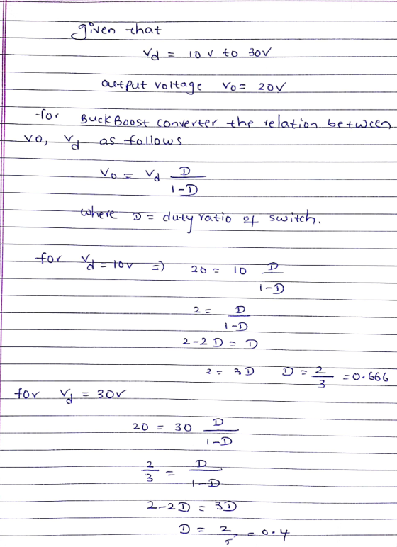
In a buck converter, consider all components to be ideal. Let the output voltage level to...
In a buck converter, consider all components to be ideal. Let the output voltage level to be constant at Vo-10 V by controlling the switch duty ratio D. Calculate the minimum inductance L required to keep the converter operation in a continuous conduction mode under all conditions if the input voltage, Vd is in the range of 20- 50 V, output power, Po ≥ 10 W, and switching frequency, fs = 20 kHz.
 1. Refer to the given buck converter circuit diagram. If V is 15 V for a 15 Q load resistor, andV45V, cal culate the duty ratio D, minimum inductance L for the continuous conduction mode, typical inductance L 1.25Lmin peak-to-peak inductor ripple current Ai, average inductor current I,, maximum inductor current i,mas and minimum inductor current min iin Vin VL + icT
1. Refer to the given buck converter circuit diagram. If V is 15 V for a 15 Q...
1. Refer to the given buck converter circuit diagram. If V is 15 V for a 15 Q load resistor, andV45V, cal culate the duty ratio D, minimum inductance L for the continuous conduction mode, typical inductance L 1.25Lmin peak-to-peak inductor ripple current Ai, average inductor current I,, maximum inductor current i,mas and minimum inductor current min iin Vin VL + icT
1. Refer to the given buck converter circuit diagram. If V is 15 V for a 15 Q...
 Buck Converter Question
Q3. A Buck converter is used to produce a regulated 10V, 5A DC power supply from a variable DC source with an nominal input voltage of Vin = 20V±5V. The Buck converter switches at 250kHz, and operates entirely in the continuous conduction mode. The output filter capacitance is C1.0uF 3.a. Draw the circuit topology for the Buck converter. Ensure that your circuit includes the input DC source, the output load resistance, the switching devices (i.e. MOSFET and...
Buck Converter Question
Q3. A Buck converter is used to produce a regulated 10V, 5A DC power supply from a variable DC source with an nominal input voltage of Vin = 20V±5V. The Buck converter switches at 250kHz, and operates entirely in the continuous conduction mode. The output filter capacitance is C1.0uF 3.a. Draw the circuit topology for the Buck converter. Ensure that your circuit includes the input DC source, the output load resistance, the switching devices (i.e. MOSFET and...
 QUESTION 3 In the DC-DC buck-boost converter shown in next page assume that all the components are ideal and the converter is operating in continuous conduction mode and is in steady-state (a) Derive the conversion ratio of WI - Draw the circuit diagram when the switch is in on and off states. Use small ripple approximation for your analysis Sketch the current through and the voltage across the inductor when the switch is in on and off states. Include all...
 3. a) Consider a boost converter shown in the figure below. Briefly explain the principle of operation of the circuit as a step-up converter, ie, how the input voltage is stepped up and how energy transfer occurs from input to the output in each cycle. Find expressions for vi(l) when the switch is closed and when it is off. Sketch it for one eycle and find its average value, Vu. Find the relationship between input and output voltages by setting...
 Please help in this question conserning the buck-boost
converter
4. a. Draw a buck-boost converter to be implemented with an IGBT and diode b. Suggest suitable component values if such a converter is to serve resistive loads between 15 W and 30 W with a constant 8 V output, when the converter's input can vary between 5 V and 12 V. The output peak-to-peak voltage ripple should be less than 5% of the output voltage. The converter should operate in...
Please help in this question conserning the buck-boost
converter
4. a. Draw a buck-boost converter to be implemented with an IGBT and diode b. Suggest suitable component values if such a converter is to serve resistive loads between 15 W and 30 W with a constant 8 V output, when the converter's input can vary between 5 V and 12 V. The output peak-to-peak voltage ripple should be less than 5% of the output voltage. The converter should operate in...
 The following circuit is a buck-boost converter where M1 functions as a switch. a. Describe how the converter works when M1 is switched on and off. b. Provide proof that V where D is the duty cycle controlled by the MOSFET, M1. 1-D Ignore the voltage drop across the transistor and the diode. D1 Vin C1 Gate drive circuit L1 RL c. Plot the transistor current, the inductor current, the capacitor current, and the load current as a function of...
Most questions answered within 3 hours.
-
The Problem: The Case of the Harmonizing Vacations
Your CEO is exploring partnering with a European...
asked 44 minutes ago -
A chemical equation is balanced by adding coefficients in front
of some formulas so that the...
asked 43 minutes ago -
From the literature (reference your sources): What are the
lattice parameters of calcite and aragonite? Why...
asked 1 hour ago -
Your system is rejecting the question am asking which is
preceded by a case study. It...
asked 1 hour ago -
3. On January 2, 2000, Larry creates a trust with himself as
trustee. Larry as trustee...
asked 1 hour ago -
A member of the volleyball team spikes the ball. During this
process, she changes the velocity...
asked 1 hour ago -
Are adult gamers less likely to use a gaming console (Xbox,
PlayStation, Wii, etc...) than teen...
asked 2 hours ago -
The University of
Texas recently reported that 43% of college students aged 18-24
would spend their...
asked 2 hours ago -
The length of stay at a specific emergency department in
Phoenix, Arizona, in 2009 had a...
asked 1 hour ago -
. Please give the mechanism for this type of problem. Step by
Step
The toxin that...
asked 1 hour ago -
If you have a 1M stock solution and you want to dilute 1 :10
with water,...
asked 1 hour ago -
In a load instruction, the effective address is obtained by
A) Retriving the address from a...
asked 1 hour ago