
Homework Answers


Add Answer to:
QUESTION 3 In the DC-DC buck-boost converter shown in next page assume that all the components...
Following figure shows the circuit diagram for a buck-boost converter for switch off and switch o...
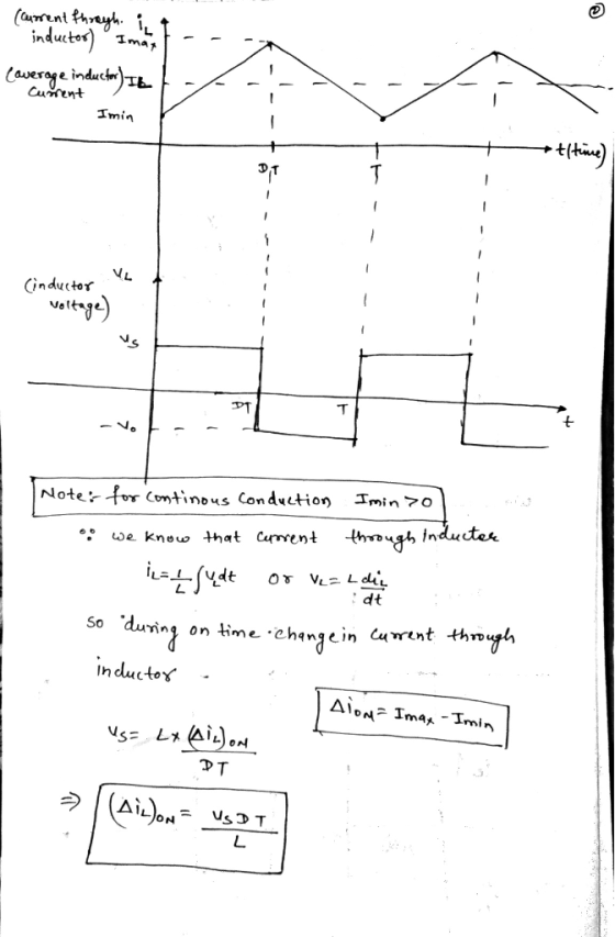
 Following figure shows the circuit diagram for a buck-boost converter for switch off and switch on. The plots for inductor voltage Vl and inductor current iL are also shown. The average value of i, is denoted by I1, average output current is -l and average input current is ld. Similarly, the average value of u1 is denoted by V1, output voltage is-, and input DC voltage is Va. Time period of the switch is Ts 1/f and its duty cycle...
Buck Converter Question Q3. A Buck converter is used to produce a regulated 10V, 5A DC...
 Buck Converter Question
Q3. A Buck converter is used to produce a regulated 10V, 5A DC power supply from a variable DC source with an nominal input voltage of Vin = 20V±5V. The Buck converter switches at 250kHz, and operates entirely in the continuous conduction mode. The output filter capacitance is C1.0uF 3.a. Draw the circuit topology for the Buck converter. Ensure that your circuit includes the input DC source, the output load resistance, the switching devices (i.e. MOSFET and...
Buck Converter Question
Q3. A Buck converter is used to produce a regulated 10V, 5A DC power supply from a variable DC source with an nominal input voltage of Vin = 20V±5V. The Buck converter switches at 250kHz, and operates entirely in the continuous conduction mode. The output filter capacitance is C1.0uF 3.a. Draw the circuit topology for the Buck converter. Ensure that your circuit includes the input DC source, the output load resistance, the switching devices (i.e. MOSFET and...
Please help in this question conserning the buck-boost converter 4. a. Draw a buck-boost converter to...
 Please help in this question conserning the buck-boost
converter
4. a. Draw a buck-boost converter to be implemented with an IGBT and diode b. Suggest suitable component values if such a converter is to serve resistive loads between 15 W and 30 W with a constant 8 V output, when the converter's input can vary between 5 V and 12 V. The output peak-to-peak voltage ripple should be less than 5% of the output voltage. The converter should operate in...
Please help in this question conserning the buck-boost
converter
4. a. Draw a buck-boost converter to be implemented with an IGBT and diode b. Suggest suitable component values if such a converter is to serve resistive loads between 15 W and 30 W with a constant 8 V output, when the converter's input can vary between 5 V and 12 V. The output peak-to-peak voltage ripple should be less than 5% of the output voltage. The converter should operate in...
1. (35 points) Switch mode DC DC Converters. a. (15 points) Design a flyback DC/DC power converter to the following specifications. Assume ideal components Input Voltage Output Voltage Output Powe...
 1. (35 points) Switch mode DC DC Converters. a. (15 points) Design a flyback DC/DC power converter to the following specifications. Assume ideal components Input Voltage Output Voltage Output Power Switching frequency Maximum Current Ripple in the filter inductor Output ripple voltage: Continuous conduction 170 VDC 12 VDC 40 Watts 750 kHz 1.2 Amps Your answer should include a circuit diagram with each energy storage element labeled with its value. Label the transformer turns ratio.
1. (35 points) Switch mode...
1. (35 points) Switch mode DC DC Converters. a. (15 points) Design a flyback DC/DC power converter to the following specifications. Assume ideal components Input Voltage Output Voltage Output Power Switching frequency Maximum Current Ripple in the filter inductor Output ripple voltage: Continuous conduction 170 VDC 12 VDC 40 Watts 750 kHz 1.2 Amps Your answer should include a circuit diagram with each energy storage element labeled with its value. Label the transformer turns ratio.
1. (35 points) Switch mode...
In a Buck-Boost converter, L=25 μΗ. It is operating in dc steady state under the following
In a Buck-Boost converter, \(L=25 \mu \mathrm{H}\). It is operating in dc steady state under the following conditions: \(V_{i n}=12 \mathrm{~V}, D\) \(=0.6, P_{o}=36 \mathrm{~W}\), and \(f_{s}=400 \mathrm{kHz}\). Assume ideal components.In this Buck-Boost converter, the output load is changing. Calculate the critical value of the output load \(P_{o}\) below which the converter will enter the discontinuous conduction mode of operation.(a) Calculate \(I_{\text {L.crit }}\) and \(I_{o, \text { crit }}\)(b) Calculate \(P_{o, \text { crit }}\)
Q5. 5.a. Sketch the circuit arrangement of a DC-DC boost (step up) converter, clearly labelling each...
 Q5. 5.a. Sketch the circuit arrangement of a DC-DC boost (step up) converter, clearly labelling each circuit element [4 тarks] [Refer to lecture notes] Sketch all significant operating waveforms for this converter for continuous conduction conditions over two switching periods, in particular showing 5.b. the voltage across the main switching device and the boost diode. [2 marks the voltage across the inductor [3 тarks] the current flowing through the inductor [3 marks [Refer to lecture notes] 5.c. The DC-DC boost...
1. Refer to the given buck converter circuit diagram. If V is 15 V for a...
 1. Refer to the given buck converter circuit diagram. If V is 15 V for a 15 Q load resistor, andV45V, cal culate the duty ratio D, minimum inductance L for the continuous conduction mode, typical inductance L 1.25Lmin peak-to-peak inductor ripple current Ai, average inductor current I,, maximum inductor current i,mas and minimum inductor current min iin Vin VL + icT
1. Refer to the given buck converter circuit diagram. If V is 15 V for a 15 Q...
1. Refer to the given buck converter circuit diagram. If V is 15 V for a 15 Q load resistor, andV45V, cal culate the duty ratio D, minimum inductance L for the continuous conduction mode, typical inductance L 1.25Lmin peak-to-peak inductor ripple current Ai, average inductor current I,, maximum inductor current i,mas and minimum inductor current min iin Vin VL + icT
1. Refer to the given buck converter circuit diagram. If V is 15 V for a 15 Q...
****Please ALL answers questions with complete steps.**** 1. Analysis and design of a buck-boost converter. A...
 ****Please ALL answers questions with complete
steps.****
1. Analysis and design of a buck-boost converter. A buck-boost converter is illustrated below. + licit) + reee c= R { v(t) A practical implementation using a MOSFET and diode is illustrated below. D + Voi(t) – H + iqi(t) IT int) lic(t) iz(t) + LE vi(t) c R v(t) For this problem, you must employ the methods of inductor volt-second balance, capacitor charge balance, and the small ripple approximation as discussed in...
****Please ALL answers questions with complete
steps.****
1. Analysis and design of a buck-boost converter. A buck-boost converter is illustrated below. + licit) + reee c= R { v(t) A practical implementation using a MOSFET and diode is illustrated below. D + Voi(t) – H + iqi(t) IT int) lic(t) iz(t) + LE vi(t) c R v(t) For this problem, you must employ the methods of inductor volt-second balance, capacitor charge balance, and the small ripple approximation as discussed in...
A Buck-boost converter has an output voltage 100 V, output power 60 W and input voltage...
A Buck-boost converter has an output voltage 100 V, output power 60 W and input voltage 12 V. Switching frequency is 15 kHz. Calculate duty ratios for the switch and the diode. Find values for the inductor L and capacitor C, when the allowed output voltage ripple is ±0.15 % and the inductor current ripple is ±1 % (of the average value). If the on-time of the switch has an inaccuracy of ±50 ns, what is the new output voltage...
18 marks load with a power of 25.6 W.The cy f is 40kHz. sign a buck-boost converter to produce an output voltage of 16V a put voltage ripple must not exceed 1%. The dc input voltage is 24V. Th e swit...
 18 marks load with a power of 25.6 W.The cy f is 40kHz. sign a buck-boost converter to produce an output voltage of 16V a put voltage ripple must not exceed 1%. The dc input voltage is 24V. Th e switching frequen 121 a) the duty ratio b) Find the size of the inductor so that the maximum inductor current c) the size of the capacitor d) Assume L=1 00μH and the switching frequency fis variable. 141 121 Lma 10A...
 Following figure shows the circuit diagram for a buck-boost converter for switch off and switch on. The plots for inductor voltage Vl and inductor current iL are also shown. The average value of i, is denoted by I1, average output current is -l and average input current is ld. Similarly, the average value of u1 is denoted by V1, output voltage is-, and input DC voltage is Va. Time period of the switch is Ts 1/f and its duty cycle...
 Buck Converter Question
Q3. A Buck converter is used to produce a regulated 10V, 5A DC power supply from a variable DC source with an nominal input voltage of Vin = 20V±5V. The Buck converter switches at 250kHz, and operates entirely in the continuous conduction mode. The output filter capacitance is C1.0uF 3.a. Draw the circuit topology for the Buck converter. Ensure that your circuit includes the input DC source, the output load resistance, the switching devices (i.e. MOSFET and...
Buck Converter Question
Q3. A Buck converter is used to produce a regulated 10V, 5A DC power supply from a variable DC source with an nominal input voltage of Vin = 20V±5V. The Buck converter switches at 250kHz, and operates entirely in the continuous conduction mode. The output filter capacitance is C1.0uF 3.a. Draw the circuit topology for the Buck converter. Ensure that your circuit includes the input DC source, the output load resistance, the switching devices (i.e. MOSFET and...
 Please help in this question conserning the buck-boost
converter
4. a. Draw a buck-boost converter to be implemented with an IGBT and diode b. Suggest suitable component values if such a converter is to serve resistive loads between 15 W and 30 W with a constant 8 V output, when the converter's input can vary between 5 V and 12 V. The output peak-to-peak voltage ripple should be less than 5% of the output voltage. The converter should operate in...
Please help in this question conserning the buck-boost
converter
4. a. Draw a buck-boost converter to be implemented with an IGBT and diode b. Suggest suitable component values if such a converter is to serve resistive loads between 15 W and 30 W with a constant 8 V output, when the converter's input can vary between 5 V and 12 V. The output peak-to-peak voltage ripple should be less than 5% of the output voltage. The converter should operate in...
 1. (35 points) Switch mode DC DC Converters. a. (15 points) Design a flyback DC/DC power converter to the following specifications. Assume ideal components Input Voltage Output Voltage Output Power Switching frequency Maximum Current Ripple in the filter inductor Output ripple voltage: Continuous conduction 170 VDC 12 VDC 40 Watts 750 kHz 1.2 Amps Your answer should include a circuit diagram with each energy storage element labeled with its value. Label the transformer turns ratio.
1. (35 points) Switch mode...
1. (35 points) Switch mode DC DC Converters. a. (15 points) Design a flyback DC/DC power converter to the following specifications. Assume ideal components Input Voltage Output Voltage Output Power Switching frequency Maximum Current Ripple in the filter inductor Output ripple voltage: Continuous conduction 170 VDC 12 VDC 40 Watts 750 kHz 1.2 Amps Your answer should include a circuit diagram with each energy storage element labeled with its value. Label the transformer turns ratio.
1. (35 points) Switch mode...
 Q5. 5.a. Sketch the circuit arrangement of a DC-DC boost (step up) converter, clearly labelling each circuit element [4 тarks] [Refer to lecture notes] Sketch all significant operating waveforms for this converter for continuous conduction conditions over two switching periods, in particular showing 5.b. the voltage across the main switching device and the boost diode. [2 marks the voltage across the inductor [3 тarks] the current flowing through the inductor [3 marks [Refer to lecture notes] 5.c. The DC-DC boost...
 1. Refer to the given buck converter circuit diagram. If V is 15 V for a 15 Q load resistor, andV45V, cal culate the duty ratio D, minimum inductance L for the continuous conduction mode, typical inductance L 1.25Lmin peak-to-peak inductor ripple current Ai, average inductor current I,, maximum inductor current i,mas and minimum inductor current min iin Vin VL + icT
1. Refer to the given buck converter circuit diagram. If V is 15 V for a 15 Q...
1. Refer to the given buck converter circuit diagram. If V is 15 V for a 15 Q load resistor, andV45V, cal culate the duty ratio D, minimum inductance L for the continuous conduction mode, typical inductance L 1.25Lmin peak-to-peak inductor ripple current Ai, average inductor current I,, maximum inductor current i,mas and minimum inductor current min iin Vin VL + icT
1. Refer to the given buck converter circuit diagram. If V is 15 V for a 15 Q...
 ****Please ALL answers questions with complete
steps.****
1. Analysis and design of a buck-boost converter. A buck-boost converter is illustrated below. + licit) + reee c= R { v(t) A practical implementation using a MOSFET and diode is illustrated below. D + Voi(t) – H + iqi(t) IT int) lic(t) iz(t) + LE vi(t) c R v(t) For this problem, you must employ the methods of inductor volt-second balance, capacitor charge balance, and the small ripple approximation as discussed in...
****Please ALL answers questions with complete
steps.****
1. Analysis and design of a buck-boost converter. A buck-boost converter is illustrated below. + licit) + reee c= R { v(t) A practical implementation using a MOSFET and diode is illustrated below. D + Voi(t) – H + iqi(t) IT int) lic(t) iz(t) + LE vi(t) c R v(t) For this problem, you must employ the methods of inductor volt-second balance, capacitor charge balance, and the small ripple approximation as discussed in...
 18 marks load with a power of 25.6 W.The cy f is 40kHz. sign a buck-boost converter to produce an output voltage of 16V a put voltage ripple must not exceed 1%. The dc input voltage is 24V. Th e switching frequen 121 a) the duty ratio b) Find the size of the inductor so that the maximum inductor current c) the size of the capacitor d) Assume L=1 00μH and the switching frequency fis variable. 141 121 Lma 10A...
Most questions answered within 3 hours.
-
The Problem: The Case of the Harmonizing Vacations
Your CEO is exploring partnering with a European...
asked 20 minutes ago -
A chemical equation is balanced by adding coefficients in front
of some formulas so that the...
asked 18 minutes ago -
From the literature (reference your sources): What are the
lattice parameters of calcite and aragonite? Why...
asked 59 minutes ago -
Your system is rejecting the question am asking which is
preceded by a case study. It...
asked 1 hour ago -
3. On January 2, 2000, Larry creates a trust with himself as
trustee. Larry as trustee...
asked 1 hour ago -
A member of the volleyball team spikes the ball. During this
process, she changes the velocity...
asked 1 hour ago -
Are adult gamers less likely to use a gaming console (Xbox,
PlayStation, Wii, etc...) than teen...
asked 2 hours ago -
The University of
Texas recently reported that 43% of college students aged 18-24
would spend their...
asked 2 hours ago -
The length of stay at a specific emergency department in
Phoenix, Arizona, in 2009 had a...
asked 1 hour ago -
. Please give the mechanism for this type of problem. Step by
Step
The toxin that...
asked 1 hour ago -
If you have a 1M stock solution and you want to dilute 1 :10
with water,...
asked 1 hour ago -
In a load instruction, the effective address is obtained by
A) Retriving the address from a...
asked 1 hour ago