
Homework Answers

Add Answer to:
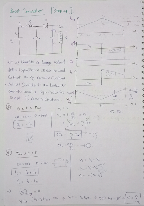
3. a) Consider a boost converter shown in the figure below. Briefly explain the principle of...
Following figure shows the circuit diagram for a buck-boost converter for switch off and switch o...
 Following figure shows the circuit diagram for a buck-boost converter for switch off and switch on. The plots for inductor voltage Vl and inductor current iL are also shown. The average value of i, is denoted by I1, average output current is -l and average input current is ld. Similarly, the average value of u1 is denoted by V1, output voltage is-, and input DC voltage is Va. Time period of the switch is Ts 1/f and its duty cycle...
A Buck-boost converter has an output voltage 100 V, output power 60 W and input voltage...
A Buck-boost converter has an output voltage 100 V, output power 60 W and input voltage 12 V. Switching frequency is 15 kHz. Calculate duty ratios for the switch and the diode. Find values for the inductor L and capacitor C, when the allowed output voltage ripple is ±0.15 % and the inductor current ripple is ±1 % (of the average value). If the on-time of the switch has an inaccuracy of ±50 ns, what is the new output voltage...
Please answer 2 and 1. Assignment No.6 10mH, C-20μF, an 1. A boost converter as the...
 Please answer 2 and 1.
Assignment No.6 10mH, C-20μF, an 1. A boost converter as the following parameters: V,-20V, L Find the current spec of the inductor for continuous current mode (Max an Min current) -20 2. Switching frequency is 50 KHz and conduction duty cycle is 0.6 a. b. Calculate the output voltage and the ripple voltage An array has been formed with three modules in a string and two strings in parallel. The overall characteristic of the array...
Please answer 2 and 1.
Assignment No.6 10mH, C-20μF, an 1. A boost converter as the following parameters: V,-20V, L Find the current spec of the inductor for continuous current mode (Max an Min current) -20 2. Switching frequency is 50 KHz and conduction duty cycle is 0.6 a. b. Calculate the output voltage and the ripple voltage An array has been formed with three modules in a string and two strings in parallel. The overall characteristic of the array...
Please help in this question conserning the buck-boost converter 4. a. Draw a buck-boost converter to...
 Please help in this question conserning the buck-boost
converter
4. a. Draw a buck-boost converter to be implemented with an IGBT and diode b. Suggest suitable component values if such a converter is to serve resistive loads between 15 W and 30 W with a constant 8 V output, when the converter's input can vary between 5 V and 12 V. The output peak-to-peak voltage ripple should be less than 5% of the output voltage. The converter should operate in...
Please help in this question conserning the buck-boost
converter
4. a. Draw a buck-boost converter to be implemented with an IGBT and diode b. Suggest suitable component values if such a converter is to serve resistive loads between 15 W and 30 W with a constant 8 V output, when the converter's input can vary between 5 V and 12 V. The output peak-to-peak voltage ripple should be less than 5% of the output voltage. The converter should operate in...
+ VDS Consider the Buck DC-to-DC converter shown above. Assume it is operated at a switching...
 + VDS Consider the Buck DC-to-DC converter shown above. Assume it is operated at a switching frequency, f 25 KHz, with a duty cycle, D- 0.4 a) Given the sketch of the inductor current, i(t), shown below, sketch the waveforms for the input current, (t), the output current, i(t), the diode current, ip(), and the capacitor current, ict).Also, compute their average, RMS and peak values. (Note: Some useful formulas are provided on the last page) 10 5 t (s) (b)...
% peak to peak ripple in Vdc- 20% determine minimum capacitance at output of boost converter 3. consider forward con...
 % peak to peak ripple in Vdc- 20%
determine minimum capacitance at output of boost converter
3. consider forward converter operating at 10khz with
the power in the table. the output voltage is 20v. the output
inductor is 90uh and turns ratio 1:1:1
I. operating mode?
ii. conduction loss in the forward converter switch if
switch resistance is 10milli ohm
Student #:- 2 125 Consider the following ACIDC folowed by a boost converner for active power factor correction, ana e...
% peak to peak ripple in Vdc- 20%
determine minimum capacitance at output of boost converter
3. consider forward converter operating at 10khz with
the power in the table. the output voltage is 20v. the output
inductor is 90uh and turns ratio 1:1:1
I. operating mode?
ii. conduction loss in the forward converter switch if
switch resistance is 10milli ohm
Student #:- 2 125 Consider the following ACIDC folowed by a boost converner for active power factor correction, ana e...
****Please ALL answers questions with complete steps.**** 1. Analysis and design of a buck-boost converter. A...
 ****Please ALL answers questions with complete
steps.****
1. Analysis and design of a buck-boost converter. A buck-boost converter is illustrated below. + licit) + reee c= R { v(t) A practical implementation using a MOSFET and diode is illustrated below. D + Voi(t) – H + iqi(t) IT int) lic(t) iz(t) + LE vi(t) c R v(t) For this problem, you must employ the methods of inductor volt-second balance, capacitor charge balance, and the small ripple approximation as discussed in...
****Please ALL answers questions with complete
steps.****
1. Analysis and design of a buck-boost converter. A buck-boost converter is illustrated below. + licit) + reee c= R { v(t) A practical implementation using a MOSFET and diode is illustrated below. D + Voi(t) – H + iqi(t) IT int) lic(t) iz(t) + LE vi(t) c R v(t) For this problem, you must employ the methods of inductor volt-second balance, capacitor charge balance, and the small ripple approximation as discussed in...
2. Renewable energy system requires a boost converter with input voltage variation of 18 V to 42 ...
 2. Renewable energy system requires a boost converter with input voltage variation of 18 V to 42 V (de) and gives output of 120 V at 0.6 kW. For the converter the switching frequency is set at 50 kHz. a) Find the operating duty cycle range for each switch of the converter0 marks b) 196 What is the inductor value which should keep inductor current variation below under all input voltages [30 marks] c) Find the capacitor value which should...
1) (6 points) It is desired to design a 50 W buck-boost converter to regulate its...
 1) (6 points) It is desired to design a 50 W buck-boost converter to regulate its output voltage at 26V from a solar panel whose output voltage varies between 20 and 40 V. The desired switching frequency is 20 kHz. The ripple current in the inductor should remain within +/-0.1 A, and the output voltage ripple should not exceed +/- 2%. a. Determine the duty cycle range for operating this converter. b. Design this buck-boost converter by finding lower limits...
5. Consider the the SEPIC converter shown in of Fig. 4 о, 01 Figure 4: Sepic...
 5. Consider the the SEPIC converter shown in of Fig. 4 о, 01 Figure 4: Sepic Converter a) Sketch the diode current waveform for CCM operation. Find its peak value, in terms of the ripple magnitudes ΔΙ.and Δ1L2 and the dc components li and 12 of the two inductor currents Ii(t) and I2(t) respectively b) Derive an expression for the conditions under which the SEPIC operates in the discontinuous conduction mode. Express your result in the form K< Keni(D) and...
 Following figure shows the circuit diagram for a buck-boost converter for switch off and switch on. The plots for inductor voltage Vl and inductor current iL are also shown. The average value of i, is denoted by I1, average output current is -l and average input current is ld. Similarly, the average value of u1 is denoted by V1, output voltage is-, and input DC voltage is Va. Time period of the switch is Ts 1/f and its duty cycle...
 Please answer 2 and 1.
Assignment No.6 10mH, C-20μF, an 1. A boost converter as the following parameters: V,-20V, L Find the current spec of the inductor for continuous current mode (Max an Min current) -20 2. Switching frequency is 50 KHz and conduction duty cycle is 0.6 a. b. Calculate the output voltage and the ripple voltage An array has been formed with three modules in a string and two strings in parallel. The overall characteristic of the array...
Please answer 2 and 1.
Assignment No.6 10mH, C-20μF, an 1. A boost converter as the following parameters: V,-20V, L Find the current spec of the inductor for continuous current mode (Max an Min current) -20 2. Switching frequency is 50 KHz and conduction duty cycle is 0.6 a. b. Calculate the output voltage and the ripple voltage An array has been formed with three modules in a string and two strings in parallel. The overall characteristic of the array...
 Please help in this question conserning the buck-boost
converter
4. a. Draw a buck-boost converter to be implemented with an IGBT and diode b. Suggest suitable component values if such a converter is to serve resistive loads between 15 W and 30 W with a constant 8 V output, when the converter's input can vary between 5 V and 12 V. The output peak-to-peak voltage ripple should be less than 5% of the output voltage. The converter should operate in...
Please help in this question conserning the buck-boost
converter
4. a. Draw a buck-boost converter to be implemented with an IGBT and diode b. Suggest suitable component values if such a converter is to serve resistive loads between 15 W and 30 W with a constant 8 V output, when the converter's input can vary between 5 V and 12 V. The output peak-to-peak voltage ripple should be less than 5% of the output voltage. The converter should operate in...
 + VDS Consider the Buck DC-to-DC converter shown above. Assume it is operated at a switching frequency, f 25 KHz, with a duty cycle, D- 0.4 a) Given the sketch of the inductor current, i(t), shown below, sketch the waveforms for the input current, (t), the output current, i(t), the diode current, ip(), and the capacitor current, ict).Also, compute their average, RMS and peak values. (Note: Some useful formulas are provided on the last page) 10 5 t (s) (b)...
 % peak to peak ripple in Vdc- 20%
determine minimum capacitance at output of boost converter
3. consider forward converter operating at 10khz with
the power in the table. the output voltage is 20v. the output
inductor is 90uh and turns ratio 1:1:1
I. operating mode?
ii. conduction loss in the forward converter switch if
switch resistance is 10milli ohm
Student #:- 2 125 Consider the following ACIDC folowed by a boost converner for active power factor correction, ana e...
% peak to peak ripple in Vdc- 20%
determine minimum capacitance at output of boost converter
3. consider forward converter operating at 10khz with
the power in the table. the output voltage is 20v. the output
inductor is 90uh and turns ratio 1:1:1
I. operating mode?
ii. conduction loss in the forward converter switch if
switch resistance is 10milli ohm
Student #:- 2 125 Consider the following ACIDC folowed by a boost converner for active power factor correction, ana e...
 ****Please ALL answers questions with complete
steps.****
1. Analysis and design of a buck-boost converter. A buck-boost converter is illustrated below. + licit) + reee c= R { v(t) A practical implementation using a MOSFET and diode is illustrated below. D + Voi(t) – H + iqi(t) IT int) lic(t) iz(t) + LE vi(t) c R v(t) For this problem, you must employ the methods of inductor volt-second balance, capacitor charge balance, and the small ripple approximation as discussed in...
****Please ALL answers questions with complete
steps.****
1. Analysis and design of a buck-boost converter. A buck-boost converter is illustrated below. + licit) + reee c= R { v(t) A practical implementation using a MOSFET and diode is illustrated below. D + Voi(t) – H + iqi(t) IT int) lic(t) iz(t) + LE vi(t) c R v(t) For this problem, you must employ the methods of inductor volt-second balance, capacitor charge balance, and the small ripple approximation as discussed in...
 2. Renewable energy system requires a boost converter with input voltage variation of 18 V to 42 V (de) and gives output of 120 V at 0.6 kW. For the converter the switching frequency is set at 50 kHz. a) Find the operating duty cycle range for each switch of the converter0 marks b) 196 What is the inductor value which should keep inductor current variation below under all input voltages [30 marks] c) Find the capacitor value which should...
 1) (6 points) It is desired to design a 50 W buck-boost converter to regulate its output voltage at 26V from a solar panel whose output voltage varies between 20 and 40 V. The desired switching frequency is 20 kHz. The ripple current in the inductor should remain within +/-0.1 A, and the output voltage ripple should not exceed +/- 2%. a. Determine the duty cycle range for operating this converter. b. Design this buck-boost converter by finding lower limits...
 5. Consider the the SEPIC converter shown in of Fig. 4 о, 01 Figure 4: Sepic Converter a) Sketch the diode current waveform for CCM operation. Find its peak value, in terms of the ripple magnitudes ΔΙ.and Δ1L2 and the dc components li and 12 of the two inductor currents Ii(t) and I2(t) respectively b) Derive an expression for the conditions under which the SEPIC operates in the discontinuous conduction mode. Express your result in the form K< Keni(D) and...
Most questions answered within 3 hours.
-
D. A student completed 20 courses in the School of Arts and
Sciences. Her grades in...
asked 13 minutes ago -
teo
pucks moving on a frictionless air table are about to collide. the
1.5 kg puck...
asked 18 minutes ago -
Problem #1
The area between Z = 0 and Z = 2.50
The area between Z...
asked 1 hour ago -
1. What is the meaning of the term communication style?
2. What are the benefits to...
asked 1 hour ago -
9.) You are buying a car that cost $26,500. You make payments of
$412 each month...
asked 1 hour ago -
. Suppose a discrete random variable has probability
distribution
P(x) = .2 if x = 0...
asked 2 hours ago -
Under the influence of its drive force, a snowmobile is moving
at a constant velocity along...
asked 3 hours ago -
Why do organizations decline? What steps can top
management take to halt, decline, and restore organizational...
asked 3 hours ago -
What mechanisms Drive speciation??
(I.e. what was Dawins theory on the orgin of species, and how...
asked 4 hours ago -
The manager at a car assembly plant believes that the mean
assembly time for a car...
asked 5 hours ago -
Which of the following is true of electron capture?
A) It decreases the nuclide's mass number...
asked 7 hours ago -
Assuming an efficiency of 43.10%, calculate the actual yield of
magnesium nitrate formed from 114.9 g...
asked 7 hours ago