
Homework Answers
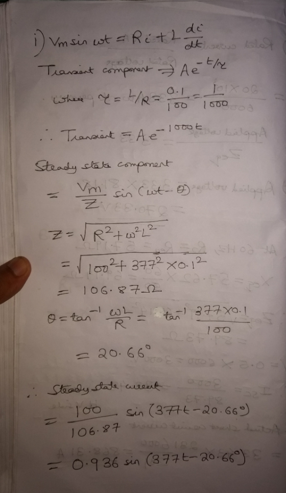
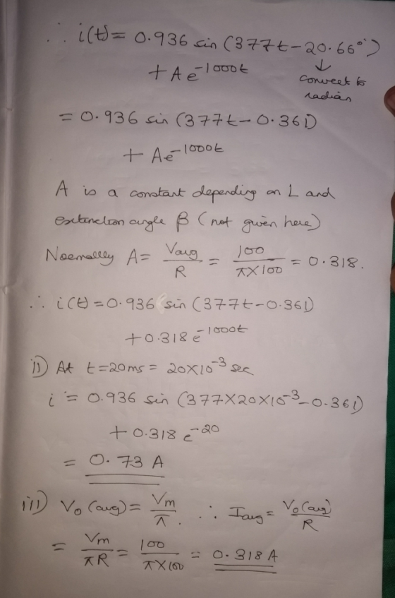
The differential equation needs to be solved just to get i(t)
Also note average load current = average load voltage / R as L has no average voltage.
Add Answer to:
Q2) A single phase half-wave uncontrolled rectifier with RL load is shown below With R-1000 L 01H w-377rad/s and V 1...
please show steps and list the electronic component with thier values please thank you in advance In this project an uncontrolled full-wave bridge rectifier with RL-Source load will be designed....
 please show steps and list the electronic component with thier
values please
thank you in advance
In this project an uncontrolled full-wave bridge rectifier with RL-Source load will be designed. The load current is continuous and the ac source is given to be Vm 240 V at 50 Hz. Design rectifier circuit, which has the following constraints: a5) Design the circuit and calculate the parameters of the rectifier for Vde 40 Volt power absorbed by the resistor is 350 W....
please show steps and list the electronic component with thier
values please
thank you in advance
In this project an uncontrolled full-wave bridge rectifier with RL-Source load will be designed. The load current is continuous and the ac source is given to be Vm 240 V at 50 Hz. Design rectifier circuit, which has the following constraints: a5) Design the circuit and calculate the parameters of the rectifier for Vde 40 Volt power absorbed by the resistor is 350 W....
1. A 50 Hz 3-phase Have wave uncontrolled rectifier circuit is used to supply a resistive load of...
 1. A 50 Hz 3-phase Have wave uncontrolled rectifier circuit is used to supply a resistive load of 100 ohms. The supply is unbalanced and defined as v.-127.28 cos (ot) V 127.28 sin (ot-0.5236) V n63.64 cos (ot+2.0944) V a) Draw the circuit diagram. b) Draw the three phase voltages wave forms. c) Use phasor diagram or any other method to obtain the line voltages v and d) Draw the line voltages v and v wave forms. e) Derive an...
A controlled half-wave rectifier has an RL load with R 20 ohm and L 40 mH....
A controlled half-wave rectifier has an RL load with R 20 ohm and L 40 mH. The source is 120 V rms at 60 Hz The delay angle required to produce an average current of 2.0 A I output RMS I input RMS Apparent power and power factor Skitch Vout, Iout, and V diod
A single phase half-wave SCR rectifier is used to reduce the average voltage across a nonlinear...
 A single phase half-wave SCR rectifier is used to reduce the
average voltage across a nonlinear resistive load where the
resistive value is represented by
R = 0. 2 V^2(aver) + 5 Ω
Calculate the load average current when the source voltage is
110 V RMS and the triggering angle is 90 degrees
A single phase half-wave SCR rectifier is used to reduce the average voltage across a nonlinear resistive load where the resistive value is represented by aver Calculate...
A single phase half-wave SCR rectifier is used to reduce the
average voltage across a nonlinear resistive load where the
resistive value is represented by
R = 0. 2 V^2(aver) + 5 Ω
Calculate the load average current when the source voltage is
110 V RMS and the triggering angle is 90 degrees
A single phase half-wave SCR rectifier is used to reduce the average voltage across a nonlinear resistive load where the resistive value is represented by aver Calculate...
A single phase half wave controlled rectifier shown below operates from ideal sinusoidal source with vi...
 A single phase half wave controlled rectifier shown below
operates from ideal sinusoidal source with vi =325sinwt at 50Hz. If
the load is purely resistive, and at a certain α, the output dc
voltage is Vdc =95V, and the average
valu of the load current is 2.2A. It is required to calculate the
following:
a) The triggering angle α
b) Load resistance
c) r.m.s load current
d) dc power
is 다. Firing Circuit
A single phase half wave controlled rectifier shown below
operates from ideal sinusoidal source with vi =325sinwt at 50Hz. If
the load is purely resistive, and at a certain α, the output dc
voltage is Vdc =95V, and the average
valu of the load current is 2.2A. It is required to calculate the
following:
a) The triggering angle α
b) Load resistance
c) r.m.s load current
d) dc power
is 다. Firing Circuit
1. A half wave rectifier is supplied from a 100Vms source. For a load consisting of a 60V battery fed through a 2Ω resistor as shown in Fig. I 2Ω D+ + VR() bat Fig. 1 For the rectifier shown in Fig....
 1. A half wave rectifier is supplied from a 100Vms source. For a load consisting of a 60V battery fed through a 2Ω resistor as shown in Fig. I 2Ω D+ + VR() bat Fig. 1 For the rectifier shown in Fig. 1, determine (a) a time varying expression for the current flowing into the battery 70.7sine -30 25.1 154.9) (b) (c) the average power flow into the battery (574W) the average power dissipation in the resistor (617W) A half...
44! 15 marks] For a 380 V, 50 Hz, three-phase Half-Wave Controlled rectifier with highly inductive...
 44! 15 marks] For a 380 V, 50 Hz, three-phase Half-Wave Controlled rectifier with highly inductive load. Calculate average voltage for firing angle 90°. Is the current continuous or discontinuous and why? what w te pall level wllige
b. Consider the single-phase fully controlled of thyristor bridge rectifier supplies a load consists of R-L...
 b. Consider the single-phase fully controlled of thyristor bridge rectifier supplies a load consists of R-L load and Vee in series as shown in Figure Q2 (b). The parameters for this circuit are as follows: supply voltage is 120 Vrms at 60 Hz, DC voltage, Voe equal to 10 v. i. Sketch the waveforms for output voltage, thyristor current, diode current and output current (CO2: PO2 - 5 marks) Calculate the output voltage, Va at a = Tt/2. (CO2: PO2...
Problem 3 (40 points): A single-phase half-wave rectifier shown in the following figure has a pure...
 Problem 3 (40 points): A single-phase half-wave rectifier shown in the following figure has a pure resistive load of RL112. Assume Vm 311V, f- 60Hz. (1) Determine the efficiency, the FF, the RF, the TUF, the PIV of the diode, the CF of the input currernt and the input PF (2) Design a C-filter so that the ripple factor of the output voltage is less than 5%; (3) With the value of capacitor C determined from (2), calculate the average...
Consider the single-phase full-wave rectifier circuit shown below with a sinusoidal input vs 120 Vrms at...
 Consider the single-phase full-wave rectifier circuit shown below with a sinusoidal input vs 120 Vrms at 60 Hz and a load R= 250 TiD DAZ 40 AD AD ww D (a) (b) Consider adding a filter capacitor to the full-wave rectifier in Problem 3 to reduce the output ripple (a) Calculate the minimum value of capacitance required to reduce the output voltage ripple to 1 % of the average value (b) Calculate the average output current (c) Calculate the average...
 please show steps and list the electronic component with thier
values please
thank you in advance
In this project an uncontrolled full-wave bridge rectifier with RL-Source load will be designed. The load current is continuous and the ac source is given to be Vm 240 V at 50 Hz. Design rectifier circuit, which has the following constraints: a5) Design the circuit and calculate the parameters of the rectifier for Vde 40 Volt power absorbed by the resistor is 350 W....
please show steps and list the electronic component with thier
values please
thank you in advance
In this project an uncontrolled full-wave bridge rectifier with RL-Source load will be designed. The load current is continuous and the ac source is given to be Vm 240 V at 50 Hz. Design rectifier circuit, which has the following constraints: a5) Design the circuit and calculate the parameters of the rectifier for Vde 40 Volt power absorbed by the resistor is 350 W....
 1. A 50 Hz 3-phase Have wave uncontrolled rectifier circuit is used to supply a resistive load of 100 ohms. The supply is unbalanced and defined as v.-127.28 cos (ot) V 127.28 sin (ot-0.5236) V n63.64 cos (ot+2.0944) V a) Draw the circuit diagram. b) Draw the three phase voltages wave forms. c) Use phasor diagram or any other method to obtain the line voltages v and d) Draw the line voltages v and v wave forms. e) Derive an...
 A single phase half-wave SCR rectifier is used to reduce the
average voltage across a nonlinear resistive load where the
resistive value is represented by
R = 0. 2 V^2(aver) + 5 Ω
Calculate the load average current when the source voltage is
110 V RMS and the triggering angle is 90 degrees
A single phase half-wave SCR rectifier is used to reduce the average voltage across a nonlinear resistive load where the resistive value is represented by aver Calculate...
A single phase half-wave SCR rectifier is used to reduce the
average voltage across a nonlinear resistive load where the
resistive value is represented by
R = 0. 2 V^2(aver) + 5 Ω
Calculate the load average current when the source voltage is
110 V RMS and the triggering angle is 90 degrees
A single phase half-wave SCR rectifier is used to reduce the average voltage across a nonlinear resistive load where the resistive value is represented by aver Calculate...
 A single phase half wave controlled rectifier shown below
operates from ideal sinusoidal source with vi =325sinwt at 50Hz. If
the load is purely resistive, and at a certain α, the output dc
voltage is Vdc =95V, and the average
valu of the load current is 2.2A. It is required to calculate the
following:
a) The triggering angle α
b) Load resistance
c) r.m.s load current
d) dc power
is 다. Firing Circuit
A single phase half wave controlled rectifier shown below
operates from ideal sinusoidal source with vi =325sinwt at 50Hz. If
the load is purely resistive, and at a certain α, the output dc
voltage is Vdc =95V, and the average
valu of the load current is 2.2A. It is required to calculate the
following:
a) The triggering angle α
b) Load resistance
c) r.m.s load current
d) dc power
is 다. Firing Circuit
 1. A half wave rectifier is supplied from a 100Vms source. For a load consisting of a 60V battery fed through a 2Ω resistor as shown in Fig. I 2Ω D+ + VR() bat Fig. 1 For the rectifier shown in Fig. 1, determine (a) a time varying expression for the current flowing into the battery 70.7sine -30 25.1 154.9) (b) (c) the average power flow into the battery (574W) the average power dissipation in the resistor (617W) A half...
 44! 15 marks] For a 380 V, 50 Hz, three-phase Half-Wave Controlled rectifier with highly inductive load. Calculate average voltage for firing angle 90°. Is the current continuous or discontinuous and why? what w te pall level wllige
 b. Consider the single-phase fully controlled of thyristor bridge rectifier supplies a load consists of R-L load and Vee in series as shown in Figure Q2 (b). The parameters for this circuit are as follows: supply voltage is 120 Vrms at 60 Hz, DC voltage, Voe equal to 10 v. i. Sketch the waveforms for output voltage, thyristor current, diode current and output current (CO2: PO2 - 5 marks) Calculate the output voltage, Va at a = Tt/2. (CO2: PO2...
 Problem 3 (40 points): A single-phase half-wave rectifier shown in the following figure has a pure resistive load of RL112. Assume Vm 311V, f- 60Hz. (1) Determine the efficiency, the FF, the RF, the TUF, the PIV of the diode, the CF of the input currernt and the input PF (2) Design a C-filter so that the ripple factor of the output voltage is less than 5%; (3) With the value of capacitor C determined from (2), calculate the average...
 Consider the single-phase full-wave rectifier circuit shown below with a sinusoidal input vs 120 Vrms at 60 Hz and a load R= 250 TiD DAZ 40 AD AD ww D (a) (b) Consider adding a filter capacitor to the full-wave rectifier in Problem 3 to reduce the output ripple (a) Calculate the minimum value of capacitance required to reduce the output voltage ripple to 1 % of the average value (b) Calculate the average output current (c) Calculate the average...
Most questions answered within 3 hours.
-
The neighborhood kids set up an outdoor lemonade stand in
Maryland in June. They find that...
asked 2 minutes from now -
9. A company has a beginning inventory of 4,000 units. The
company estimates it will sell...
asked 11 minutes ago -
A patient goes to the doctor's office with symptoms of a urinary
tract infection and provides...
asked 13 minutes ago -
When responding to the essay questions, be sure to cite any
material you obtained from a...
asked 13 minutes ago -
The energy of an electron in a 2.25-eV-deep potential well is
1.50 eV.At what distance into...
asked 15 minutes ago -
Q1:Which three evolutionary innovations are present in land
plants (but not all land plants) that allowed...
asked 18 minutes ago -
Lymphosarcoma is
extremely rare. Risk factors for the disease are largely unknown.
What kind of study...
asked 20 minutes ago -
The solubility of benzoic acid in water is:
0.29g/100mL at 20°C
6.8g/100mL at 100°C
a) What...
asked 21 minutes ago -
Which food law was passed in 1996 and changed how pesticide
residues on food were regulated...
asked 39 minutes ago -
companies either hire outside programmers to
write_____ software or use their own internal developers.
asked 39 minutes ago -
A magnetic dipole m(t) = m_0*cos(ωt) can be
described as current density j(r,t) = −cm(t) ×...
asked 38 minutes ago -
Probabilities and Counting. Yahtzee is a game that involves six
fair dice. When rolling all six...
asked 40 minutes ago