

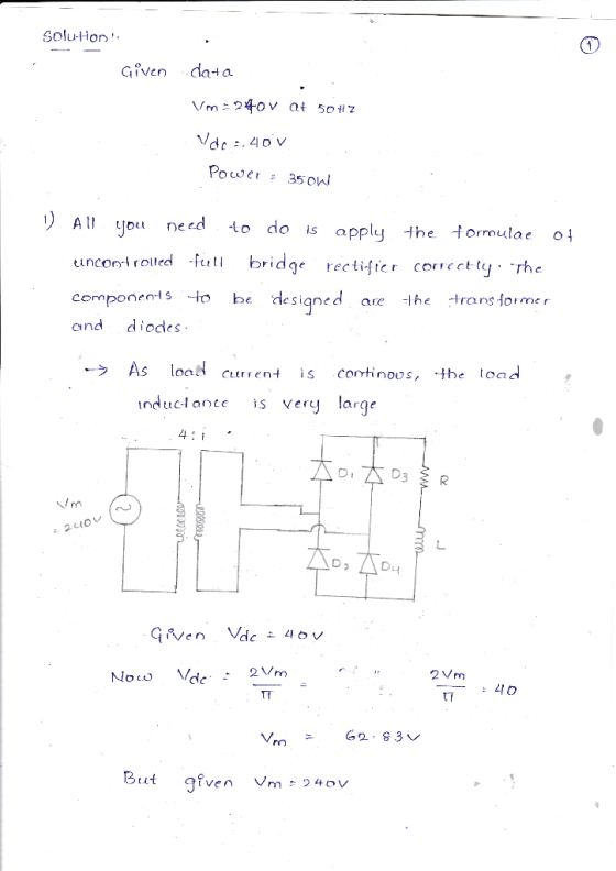
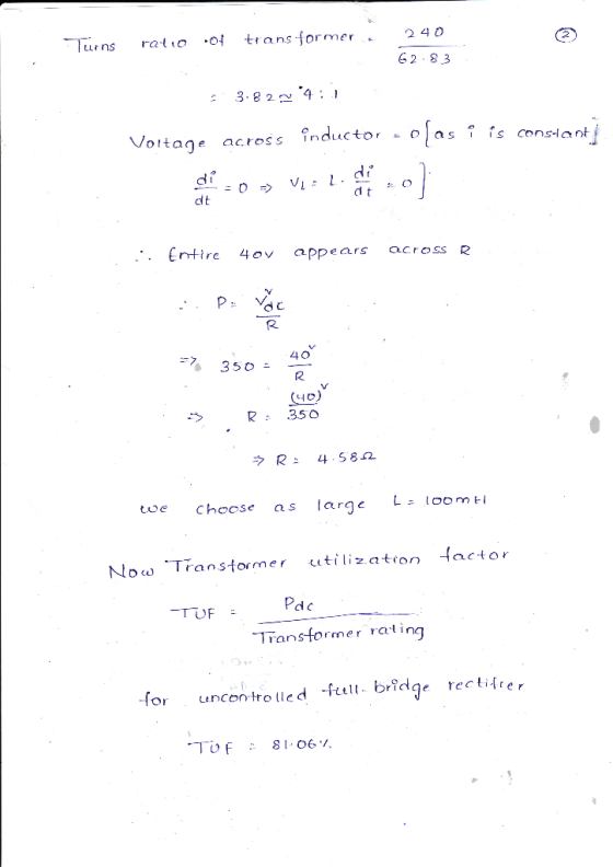
a5) Design the circuit and calculate the parameters of the rectifier for Vde 40 Volt power absorbed by the resistor is 350 W. Then test the rectifier hardware and show that theoretical and practical results are the same.
Homework Answers

Add Answer to:
please show steps and list the electronic component with thier values please thank you in advance In this project an uncontrolled full-wave bridge rectifier with RL-Source load will be designed....
6.26. Calculate the average power delivered to the load for the full-wave bridge rectifier circuit in...
 6.26. Calculate the average power delivered to the load for the full-wave bridge rectifier circuit in Figure 6.9 if the diode is ideal, Vac is sinusoidal with a peak value of 170 V, and the load resistor has a value of 100 12. AC D4 -DC 4 +DC 4 D AC RL FIGURE 6.9 Full-wave bridge rectifier circuit.
!!!URGENT!!! 1. The full-wave controlled bridge rectifier shown has an ac input of 220 V rms...
 !!!URGENT!!!
1. The full-wave controlled bridge rectifier shown has an ac input of 220 V rms at 50 Hz and a 92 load resistor. The delay angle is 45º. Determine the average current in the load, the power absorbed by the load and the source voltamperes. sino
!!!URGENT!!!
1. The full-wave controlled bridge rectifier shown has an ac input of 220 V rms at 50 Hz and a 92 load resistor. The delay angle is 45º. Determine the average current in the load, the power absorbed by the load and the source voltamperes. sino
Design a FULL WAVE BRIDGE RECTIFIER circuit that will: Take 120volts ac, 60 hz, sinusoidal waveform...
 Design a FULL WAVE BRIDGE RECTIFIER circuit that will:
Take 120volts ac, 60 hz, sinusoidal waveform and convert
it to a “regulated “dc value
giving 12 volts +, - 1 volt across a 2000-ohm output
load resistor with no more than 2%
ripple voltage.
You may assume:
a. An ideal power transformer as discussed in class.
b. For hand computations, you must assume a diode given by
Figure 4.8 page 185.
c. A filter capacitor sized per the textbook equation...
Design a FULL WAVE BRIDGE RECTIFIER circuit that will:
Take 120volts ac, 60 hz, sinusoidal waveform and convert
it to a “regulated “dc value
giving 12 volts +, - 1 volt across a 2000-ohm output
load resistor with no more than 2%
ripple voltage.
You may assume:
a. An ideal power transformer as discussed in class.
b. For hand computations, you must assume a diode given by
Figure 4.8 page 185.
c. A filter capacitor sized per the textbook equation...
Design a FULL WAVE BRIDGE RECTIFIER circuit that will: Take 120volts ac, 60 hz, sinusoidal wavef...
Design a FULL WAVE BRIDGE RECTIFIER circuit that will: Take 120volts ac, 60 hz, sinusoidal waveform from the wall power and convert it to a “regulated” dc value giving 15 volts +, - 1.0 volts across a 1200-ohm output load resistor with no more than 2% ripple voltage, all at a total component parts cost of less than $175.00 (US$). Your design process/ analysis is to be conducted by hand. Consider for this design task: Assume an ideal transformer and...
 6.26. Calculate the average power delivered to the load for the full-wave bridge rectifier circuit in Figure 6.9 if the diode is ideal, Vac is sinusoidal with a peak value of 170 V, and the load resistor has a value of 100 12. AC D4 -DC 4 +DC 4 D AC RL FIGURE 6.9 Full-wave bridge rectifier circuit.
 !!!URGENT!!!
1. The full-wave controlled bridge rectifier shown has an ac input of 220 V rms at 50 Hz and a 92 load resistor. The delay angle is 45º. Determine the average current in the load, the power absorbed by the load and the source voltamperes. sino
!!!URGENT!!!
1. The full-wave controlled bridge rectifier shown has an ac input of 220 V rms at 50 Hz and a 92 load resistor. The delay angle is 45º. Determine the average current in the load, the power absorbed by the load and the source voltamperes. sino
 Design a FULL WAVE BRIDGE RECTIFIER circuit that will:
Take 120volts ac, 60 hz, sinusoidal waveform and convert
it to a “regulated “dc value
giving 12 volts +, - 1 volt across a 2000-ohm output
load resistor with no more than 2%
ripple voltage.
You may assume:
a. An ideal power transformer as discussed in class.
b. For hand computations, you must assume a diode given by
Figure 4.8 page 185.
c. A filter capacitor sized per the textbook equation...
Design a FULL WAVE BRIDGE RECTIFIER circuit that will:
Take 120volts ac, 60 hz, sinusoidal waveform and convert
it to a “regulated “dc value
giving 12 volts +, - 1 volt across a 2000-ohm output
load resistor with no more than 2%
ripple voltage.
You may assume:
a. An ideal power transformer as discussed in class.
b. For hand computations, you must assume a diode given by
Figure 4.8 page 185.
c. A filter capacitor sized per the textbook equation...
Most questions answered within 3 hours.
-
4. How many input & output Key Value Pairs are passed into,
and emitted out of...
asked 22 minutes ago -
B. If compound Y has approximately the same values of solubility
in toluene as compound X,...
asked 11 minutes ago -
Oscar Inc. has inventory in Japan valued at 39,051,000 Yen one
year ago. One year ago...
asked 18 minutes ago -
If Canada suffered from "fundamental disequilibrium," and its
government choose not to devalue its currency, a...
asked 27 minutes ago -
Why would your heart not function well if constructed of
skeletal muscle? What is the particular...
asked 30 minutes ago -
Please respond to this essay question in full essay form for
Chemistry 1102 Organic and Biochemistry:...
asked 31 minutes ago -
Determine the head loss and velocity of flow in a water supply main
of 15.0 cm...
asked 33 minutes ago -
A marketing executive who knowingly authorizes a shoddy
defective product to be brought to market is...
asked 42 minutes ago -
Write a psudocode:
1. Define a function called authorize that takes in 2 strings,
uName, and...
asked 46 minutes ago -
What Hall voltage (in mV) is produced by a 0.180 T field applied
across a 2.60...
asked 45 minutes ago -
What mass of ethylene glycol (C2H6O2) must be added to 211.0 g
of water to obtain...
asked 48 minutes ago -
Mary's employer has a defined benefits retirement plan, which
pay 3.2% of her last year's salary...
asked 51 minutes ago