
Homework Answers

Add Answer to:
ELE 2603 Signal Conditioning Exercises 37. A Wheatstone bridge is shown in the figure below is...
Signal Conditioning Exercises ELE 2603 27. A sensor is connected in a voltage divider configuration as...
 Signal Conditioning Exercises ELE 2603 27. A sensor is connected in a voltage divider configuration as R2. If the sensor has a transfer function of 0.2 0/°C. if R1 250 Q and Vs 5 V. What is the temperature of the sensor when VD 1.25 V? R1 Vs W VD R2 Answer 28. Find Vab in mV for the circuit shown when R1- 350 0, R2 500 , R3 400 Q and R4 is flow sensor with a transfer function...
Quarter Bridge configuration on Wheatstone Bridge has only one sensor. If with its configuration voltage is...
Quarter Bridge configuration on Wheatstone Bridge has only one sensor. If with its configuration voltage is given 100 Volt, R1 = 80 Ω R2 = 80 Ω R3 = 480 Ω With R1 and R3 are on the upper part of Wheatstone Bridge, R2 and R4 are on the lower part of Wheatstone Bridge, determine: a) Schematic of Wheatstone Bridge, strain gauge sensor, and Op-Amp for measuring a strain b) R4 so the voltage of Wheatstone is balanced c) Using...
For a Wheatstone bridge circuit, R1 is a sensor whose resistance is related to a measured...
For a Wheatstone bridge circuit, R1 is a sensor whose resistance is related to a measured variable x by the equation R1 = 20x2. If R3 = R4 = 100 Ω, and the bridge is balanced when R2 = 46 Ω, determine x.
A resistive temperature sensor Rv (calibration curve shown below) is used to measure the temperature of...
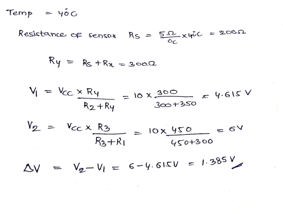
 A resistive temperature sensor Rv (calibration curve shown below) is used to measure the temperature of a process using Wheatstone bridge (Fig. 1). When the bridge is balanced, EO = OV. Then the Ry is inserted into a process whose temperature is 100C. Assume Ei = 10V, R1 = R2 = R3 = 4k12. 1. At which temperature the bridge is balanced? How much is EO at balanced mode? 2. Find the bridge output voltage E, a 3-significant figure voltmeter...
Explain using theory, why does the simulation result is shown as followed Wheatstone Bridge + inv...
 Explain using theory, why does the simulation result is shown as
followed
Wheatstone Bridge + inverting amplifier
Rf R1 R3 Rs VO R2 Rx Simulation condition 1. Parametric simulation (Vo vs R,) . Sweep AR (0-50(2) R3 R4 20k 20k ND 0 OU V1 R1 2 ND R5 R6 R7 1k uA741 GND 20k Rsweep) 20k R2 100k PARAMETERS 5.00v 4.98 4.96 4.94V 35 40 45 50 15 20 25 30 10
Rf R1 R3 Rs VO R2 Rx
Simulation...
Explain using theory, why does the simulation result is shown as
followed
Wheatstone Bridge + inverting amplifier
Rf R1 R3 Rs VO R2 Rx Simulation condition 1. Parametric simulation (Vo vs R,) . Sweep AR (0-50(2) R3 R4 20k 20k ND 0 OU V1 R1 2 ND R5 R6 R7 1k uA741 GND 20k Rsweep) 20k R2 100k PARAMETERS 5.00v 4.98 4.96 4.94V 35 40 45 50 15 20 25 30 10
Rf R1 R3 Rs VO R2 Rx
Simulation...
36) The parameters for the unbalanced Wheatstone Bridge is shown below. The current value of the...
 36) The parameters for the unbalanced Wheatstone Bridge is shown below. The current value of the 1K potentiometer is at 50%. (Center Position) What direction should the potentiometer be turned to achieve a balanced Wheatstone Bridge Vsl 12 V R1 120 R2=100 R3- 220 R3 RL R2 R4 50% A)Less than 50% C) It should remain at 50% B) Greater than 50% D) It cannot be balanced with this Potentiometer 37) The parameters for the unbalanced Wheatstone Bridge is shown...
This circuit is a Wheatstone Bridge. It is used for numerous scientific and engineering applications. Here,...
 This circuit is a Wheatstone Bridge. It is used for numerous
scientific and engineering applications. Here, R1 = 20 kΩ, R2 = 10
kΩ, R3 = 5 kΩ, and R4 = 10 kΩ. ε = 5 V.
a) Determine the Thevenin equivalent resistance RTH between
points A and B. (Hint: when we remove the power supply and short
the circuit, the wire connecting the “top” and “bottom” of the
bridge can then be drawn to go right down the center...
This circuit is a Wheatstone Bridge. It is used for numerous
scientific and engineering applications. Here, R1 = 20 kΩ, R2 = 10
kΩ, R3 = 5 kΩ, and R4 = 10 kΩ. ε = 5 V.
a) Determine the Thevenin equivalent resistance RTH between
points A and B. (Hint: when we remove the power supply and short
the circuit, the wire connecting the “top” and “bottom” of the
bridge can then be drawn to go right down the center...
A force sensor has as its output a change in resistance. The sensor forms one leg (Ri) of a basic Wheatstone bridge. The sensor resistance with no force load is 200 2, and its static sensitivity is...
 A force sensor has as its output a change in resistance. The sensor forms one leg (Ri) of a basic Wheatstone bridge. The sensor resistance with no force load is 200 2, and its static sensitivity is 0.2 ОЛ. Each arm of the bridge is initially 200 Ri R2 0) 14 13 R3 1s o O V-10 V Determine the bridge output for applied loads of 100, 200, and 350N. The bridge is operated as a deflection bridge, with an...
nanswered Question 38 011 pts The parameters for the unloaded Wheatstone Bridge is shown below Determine...
 nanswered Question 38 011 pts The parameters for the unloaded Wheatstone Bridge is shown below Determine the value of R4 so that the voltage from A to B is 1 V R4- vs1 = 12 V R1 =120 Ω R2 = 100 Ω R3= 220 Ω R1 R3 R4 orrect Answer 130 Ω
An RTD forms one arm of a Wheatstone bridge, as shown in Figure below.
 An RTD forms one arm of a Wheatstone bridge, as shown in Figure below. The RTD in a balanced is used to measure a constant temperature, with the bridge operated mode. The RTD has a resistance of 25 V at a temperature of 0°C, and a thermal coefficient of resistance, α= 0.003925°C, The value of the variable resistance R1 must be set to 37 V to balance the bridge circuit. (1) Determine the temperature of the RTD. (2) Compare this circuit to the...
 Signal Conditioning Exercises ELE 2603 27. A sensor is connected in a voltage divider configuration as R2. If the sensor has a transfer function of 0.2 0/°C. if R1 250 Q and Vs 5 V. What is the temperature of the sensor when VD 1.25 V? R1 Vs W VD R2 Answer 28. Find Vab in mV for the circuit shown when R1- 350 0, R2 500 , R3 400 Q and R4 is flow sensor with a transfer function...
 A resistive temperature sensor Rv (calibration curve shown below) is used to measure the temperature of a process using Wheatstone bridge (Fig. 1). When the bridge is balanced, EO = OV. Then the Ry is inserted into a process whose temperature is 100C. Assume Ei = 10V, R1 = R2 = R3 = 4k12. 1. At which temperature the bridge is balanced? How much is EO at balanced mode? 2. Find the bridge output voltage E, a 3-significant figure voltmeter...
 Explain using theory, why does the simulation result is shown as
followed
Wheatstone Bridge + inverting amplifier
Rf R1 R3 Rs VO R2 Rx Simulation condition 1. Parametric simulation (Vo vs R,) . Sweep AR (0-50(2) R3 R4 20k 20k ND 0 OU V1 R1 2 ND R5 R6 R7 1k uA741 GND 20k Rsweep) 20k R2 100k PARAMETERS 5.00v 4.98 4.96 4.94V 35 40 45 50 15 20 25 30 10
Rf R1 R3 Rs VO R2 Rx
Simulation...
Explain using theory, why does the simulation result is shown as
followed
Wheatstone Bridge + inverting amplifier
Rf R1 R3 Rs VO R2 Rx Simulation condition 1. Parametric simulation (Vo vs R,) . Sweep AR (0-50(2) R3 R4 20k 20k ND 0 OU V1 R1 2 ND R5 R6 R7 1k uA741 GND 20k Rsweep) 20k R2 100k PARAMETERS 5.00v 4.98 4.96 4.94V 35 40 45 50 15 20 25 30 10
Rf R1 R3 Rs VO R2 Rx
Simulation...
 36) The parameters for the unbalanced Wheatstone Bridge is shown below. The current value of the 1K potentiometer is at 50%. (Center Position) What direction should the potentiometer be turned to achieve a balanced Wheatstone Bridge Vsl 12 V R1 120 R2=100 R3- 220 R3 RL R2 R4 50% A)Less than 50% C) It should remain at 50% B) Greater than 50% D) It cannot be balanced with this Potentiometer 37) The parameters for the unbalanced Wheatstone Bridge is shown...
 This circuit is a Wheatstone Bridge. It is used for numerous
scientific and engineering applications. Here, R1 = 20 kΩ, R2 = 10
kΩ, R3 = 5 kΩ, and R4 = 10 kΩ. ε = 5 V.
a) Determine the Thevenin equivalent resistance RTH between
points A and B. (Hint: when we remove the power supply and short
the circuit, the wire connecting the “top” and “bottom” of the
bridge can then be drawn to go right down the center...
This circuit is a Wheatstone Bridge. It is used for numerous
scientific and engineering applications. Here, R1 = 20 kΩ, R2 = 10
kΩ, R3 = 5 kΩ, and R4 = 10 kΩ. ε = 5 V.
a) Determine the Thevenin equivalent resistance RTH between
points A and B. (Hint: when we remove the power supply and short
the circuit, the wire connecting the “top” and “bottom” of the
bridge can then be drawn to go right down the center...
 A force sensor has as its output a change in resistance. The sensor forms one leg (Ri) of a basic Wheatstone bridge. The sensor resistance with no force load is 200 2, and its static sensitivity is 0.2 ОЛ. Each arm of the bridge is initially 200 Ri R2 0) 14 13 R3 1s o O V-10 V Determine the bridge output for applied loads of 100, 200, and 350N. The bridge is operated as a deflection bridge, with an...
 nanswered Question 38 011 pts The parameters for the unloaded Wheatstone Bridge is shown below Determine the value of R4 so that the voltage from A to B is 1 V R4- vs1 = 12 V R1 =120 Ω R2 = 100 Ω R3= 220 Ω R1 R3 R4 orrect Answer 130 Ω
Most questions answered within 3 hours.
-
A college student is employed as a door-to-door newspaper
salesman. Historical data suggests that the student...
asked 4 minutes ago -
Considering gravitational time dilation, calculate the time that
passes in Earth’s surface while 1 hour passes...
asked 28 minutes ago -
Minitab Problem: Take the Lake Hume June rainfall data and find
use the processes outlined in...
asked 1 hour ago -
X Company is trying to decide whether to continue using old
equipment to make Product A...
asked 1 hour ago -
IN PYTHON ONLY !! Program 2: Re-work
program #5 (WeeklyHours) from the previous assignment such that...
asked 1 hour ago -
The average length of time between arrivals at a turnpike
toll-booth is 26 seconds. What is...
asked 3 hours ago -
(a) A piston at 6.1 atm contains a gas that occupies a volume of
3.5 L....
asked 4 hours ago -
Please answer true or false. Words
cannot be changed or added in to make it true...
asked 4 hours ago -
An empty test tube weighs 15.923 grams. Then,
MgCl2•6H2O is added into the test tube. After...
asked 4 hours ago -
Assume memory access is 10 units of time and disk access is
10000 units of time....
asked 5 hours ago -
1. Are all good samples random?
2. Magazines often report surveys giving statistics such as “63%...
asked 5 hours ago -
Under all the various types of market structures, firms
must eventually earn some economic profits for...
asked 5 hours ago