
Homework Answers

Add Answer to:
Design a band pass filter (BPF) with a circuit shown below (ie find R, R, RF,...
For the Multi Feedback Topology Band-pass Filter circuit shown in Figure 1 below, confirm the transfer...
 For the Multi Feedback Topology Band-pass Filter circuit shown in Figure 1 below, confirm the transfer function H(s) given below 0 Figure 1: Multiple Feedback Topology Band-pass Filter (MFT BPF) Vo SR で 1 Ri R3 2R TR2C where the filter's parameters are o f: middle (center) frequency in Hz o Am: gain at middle frequency, fm, in V/V o B: bandwidth between half power frequencies in Hz o Q: quality factor. One of the nice features of this circuit...
Design an active band-pass filter such that the center frequency is Fo-2.5 kHz, bandwidth is BW...
 Design an active band-pass filter such that the center frequency is Fo-2.5 kHz, bandwidth is BW 400 Hz and gain is K-3 for Figure 10.5. Find the values for the capacitors, and resistors. Compute the theoretical values of Vout and |Av Vout / V l and record the results in Table 10.5-A. VEE -15V C1 R3 C2 R1 R2 Vout +VCC +15V Figure 10.5
A) Design a low-pass filter using the given circuitry with a cut-off value of 1 kHz and plot the ...
 a) Design a low-pass filter using the given circuitry with a cut-off value of 1 kHz and plot the frequency response curve on the given axes 1.0 0.7 0.5 in out 0.0 101 102 103 104 10s Hz b) Design a band-pass filter using the given circuitry with a bandwidth of 500 Hz and a lower cut-off value of 100 Hz, and draw the frequency response curve. Keep all resistors at the same value (i.e. Ri-R-R3-R4). 1.0 0.7 0.5 0.0...
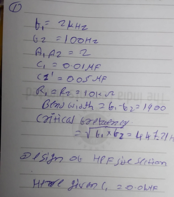
(OR) Design a wide band pass filter having fi-400 Hz, fi - 2 KHz and pass...
 (OR) Design a wide band pass filter having fi-400 Hz, fi - 2 KHz and pass band gain of 4. Find the value of 0 of the filter design and explain.
C V. Figure 2 A band-pass filter circuit This is the transfer function of a band-pass...
 C V. Figure 2 A band-pass filter circuit This is the transfer function of a band-pass filter having R = R2 //R Center frequency, a[ 1/R' R C12 radians Bandwidth B2(R, C) radians Maximum Gain Ag- R/2R Band-Pass Filter Design Design a band-pass filter to obtain f-160 Hz, B-16 Hz and o- 10. Supply voltages of +20 and -20 Volts are available. Laboratory Measurements and Results . By applying sinusoidal voltage at the input and by varying its frequency, obtain...
Design Active Band Pass Filter with the following characteristics: Gain = 10 C = 0.1uF Find...
Design Active Band Pass Filter with the following characteristics: Gain = 10 C = 0.1uF Find Rl, Rh, Rin, Rf If this was a band reject filter what would the values of R1, and R2 be?
13.60 A second-order band-pass filter is required with a center frequency of fo 54 kHz and a pass...
 13.60 A second-order band-pass filter is required with a center frequency of fo 54 kHz and a passband gain of +50 dB. If the filter is implemented using the circuit of Fig. 13.15 with C1-C2, choose appropriate values for Ri and R2. What is the resulting value of for the filter? What is its bandwidth? Ci Figure 13.15 Second-order active bandpass filter of the Sallen-Key type. R2 C2 Ri UIN OUT
13.60 A second-order band-pass filter is required with a...
13.60 A second-order band-pass filter is required with a center frequency of fo 54 kHz and a passband gain of +50 dB. If the filter is implemented using the circuit of Fig. 13.15 with C1-C2, choose appropriate values for Ri and R2. What is the resulting value of for the filter? What is its bandwidth? Ci Figure 13.15 Second-order active bandpass filter of the Sallen-Key type. R2 C2 Ri UIN OUT
13.60 A second-order band-pass filter is required with a...
Design a low pass filter with a cutoff frequency of 1 kHz +/- 100 Hz and...
Design a low pass filter with a cutoff frequency of 1 kHz +/- 100 Hz and a gain of 16.0 dB +/- 1.0 dB in the passband. The R2 and C components of the filter control the cutoff frequency, and are inversely proportional to the cutoff frequency. So decreasing the resistance or capacitance will increase the cutoff frequency. The R1 and Rf components determine the gain of the amplifier. Increasing the value of Rf will increase the gain. Increasing the...
Design a band pass filter with an RCL series circuit, with a resonant frequency of 18500...
Design a band pass filter with an RCL series circuit, with a resonant frequency of 18500 Hz and a width of 1500 rad / sec
Consider the filter shown in Figure P1 a) Show that the circuit behaves as a band-pass...
 Consider the filter shown in Figure P1 a) Show that the circuit behaves as a band-pass fiter. (Hint: Find the transfer for this circuit and show that it has the same form as the transfer function for a band-pass filter.) b) Find the center frequency, bandwidth and gain for this band-pass filter c) Find the cutoff frequencies and the quality factor for this band-pass filter. 10 u.F 5 k2 50mF 16 400 (2 Figure P1
 For the Multi Feedback Topology Band-pass Filter circuit shown in Figure 1 below, confirm the transfer function H(s) given below 0 Figure 1: Multiple Feedback Topology Band-pass Filter (MFT BPF) Vo SR で 1 Ri R3 2R TR2C where the filter's parameters are o f: middle (center) frequency in Hz o Am: gain at middle frequency, fm, in V/V o B: bandwidth between half power frequencies in Hz o Q: quality factor. One of the nice features of this circuit...
 Design an active band-pass filter such that the center frequency is Fo-2.5 kHz, bandwidth is BW 400 Hz and gain is K-3 for Figure 10.5. Find the values for the capacitors, and resistors. Compute the theoretical values of Vout and |Av Vout / V l and record the results in Table 10.5-A. VEE -15V C1 R3 C2 R1 R2 Vout +VCC +15V Figure 10.5
 a) Design a low-pass filter using the given circuitry with a cut-off value of 1 kHz and plot the frequency response curve on the given axes 1.0 0.7 0.5 in out 0.0 101 102 103 104 10s Hz b) Design a band-pass filter using the given circuitry with a bandwidth of 500 Hz and a lower cut-off value of 100 Hz, and draw the frequency response curve. Keep all resistors at the same value (i.e. Ri-R-R3-R4). 1.0 0.7 0.5 0.0...
 (OR) Design a wide band pass filter having fi-400 Hz, fi - 2 KHz and pass band gain of 4. Find the value of 0 of the filter design and explain.
 C V. Figure 2 A band-pass filter circuit This is the transfer function of a band-pass filter having R = R2 //R Center frequency, a[ 1/R' R C12 radians Bandwidth B2(R, C) radians Maximum Gain Ag- R/2R Band-Pass Filter Design Design a band-pass filter to obtain f-160 Hz, B-16 Hz and o- 10. Supply voltages of +20 and -20 Volts are available. Laboratory Measurements and Results . By applying sinusoidal voltage at the input and by varying its frequency, obtain...
 13.60 A second-order band-pass filter is required with a center frequency of fo 54 kHz and a passband gain of +50 dB. If the filter is implemented using the circuit of Fig. 13.15 with C1-C2, choose appropriate values for Ri and R2. What is the resulting value of for the filter? What is its bandwidth? Ci Figure 13.15 Second-order active bandpass filter of the Sallen-Key type. R2 C2 Ri UIN OUT
13.60 A second-order band-pass filter is required with a...
13.60 A second-order band-pass filter is required with a center frequency of fo 54 kHz and a passband gain of +50 dB. If the filter is implemented using the circuit of Fig. 13.15 with C1-C2, choose appropriate values for Ri and R2. What is the resulting value of for the filter? What is its bandwidth? Ci Figure 13.15 Second-order active bandpass filter of the Sallen-Key type. R2 C2 Ri UIN OUT
13.60 A second-order band-pass filter is required with a...
 Consider the filter shown in Figure P1 a) Show that the circuit behaves as a band-pass fiter. (Hint: Find the transfer for this circuit and show that it has the same form as the transfer function for a band-pass filter.) b) Find the center frequency, bandwidth and gain for this band-pass filter c) Find the cutoff frequencies and the quality factor for this band-pass filter. 10 u.F 5 k2 50mF 16 400 (2 Figure P1
Most questions answered within 3 hours.
-
Consider a 1.0 L buffer containing 0.092 mol L-1 HCOOH and 0.100
mol L-1 HCOO-. What...
asked 4 minutes ago -
Koch Realty has owned a vacant land with a FMV of
$775,000 and an adjusted basis...
asked 10 minutes ago -
It is estimated 29% of all adults in United States invest in
stocks and that 85%...
asked 10 minutes ago -
What does a 2-sided p value of 0.04 mean? (I am not asking if it
is...
asked 24 minutes ago -
A parallel-plate capacitor is made from two aluminum-foil
sheets, each 7.8 cmcm wide and 5.1 mmlong....
asked 25 minutes ago -
1. why is toluene a stronger nucleophile than benzene?
2.why is phenol a stronger nucleophile than...
asked 42 minutes ago -
4. How can you solve for the density of the liquid from the
slope? Please show...
asked 42 minutes ago -
when 2053 j of heat is added to 46.3 g of hexane C6H14 the
temperature increases...
asked 1 hour ago -
I need new and unique answers, please. (Use your own words,
don't copy and paste), Please...
asked 1 hour ago -
MCL 445.111 et seq. deals with Home Solicitation Sales.
MCL stands for Michigan Compiled Laws which...
asked 59 minutes ago -
Which of the following items may not create an NOL?
a.
sole proprietorship loss
b.
personal...
asked 1 hour ago -
A hypothetical solution forms between a solid and a liquid. The
values of the thermodynamic quantities...
asked 1 hour ago