(16 points) Difficulty (4/5)
A mechanical connection known as a clevis and pin is shown. The dimensions of the assembly are given as:
a = 30 mm
b = 33 mm
c = 10 mm
d = 18 mm
t = 22 mm
W = 45 mm
L = 113 mm
In order to avoid failure in the materials used to create the parts:
-The normal stress in the pin must be limited to 680 MPa.
-The shearing stress in the pin must be limited to 272 MPa.
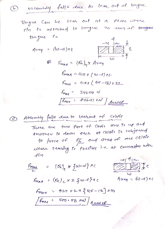
-The normal stress in the tongue must be limited to 415 MPa.
-The shearing stress in the tongue must be limited to 249
MPa.
-The normal stress in the clevis must be limited to 927 MPa.
-The shearing stress in the clevis must be limited to 370 MPa.
Find the maximum force FF that can be applied if:
(a) the assembly fails due to the pin shearing
(b) the assembly fails due to tearout of the tongue
(c) the assembly fails due to tearout of the clevis
(d) the assembly fails due to tensile failure of the tongue
(e) the assembly fails due to tensile failure of the clevis
(f) the assembly fails due to the average bearing stress between
the tongue and the pin
(g) the assembly fails due to the average bearing stress between
the clevis and the pin
(h) all of these modes of failure are considered.

(a) Fpin−shearFpin−shear =
(b) Ftongue−tearoutFtongue−tearout =
(c) Fclevis−tearoutFclevis−tearout =
(d) Ftongue−tensileFtongue−tensile =
(e) Fclevis−tensileFclevis−tensile =
(f) Ftongue−pin−bearingFtongue−pin−bearing =
(g) Fclevis−pin−bearingFclevis−pin−bearing =
(h) Foverall−allowableFoverall−allowable =
be sure to include units with your answers
neglect stress concentration effects
for parts a-g, assume the assembly doesn't fail in another mode first
assume all parts fit together with minimal clearances
Homework Answers


Add Answer to:
(16 points) Difficulty (4/5) A mechanical connection known as a clevis and pin is shown. The...
scenes M1.1 Normal, shear, and bearing stress For the pin connection shown, Pin diameter = 16...
 scenes M1.1 Normal, shear, and bearing stress For the pin connection shown, Pin diameter = 16 mm determine the normal stress acting on the gross area, the normal stress acting on the net plate area, the shear stress in the pin, and the bearing stress in the 45 kN steel plate at the pin. (Stress units MPa) Pin 70 mm Gusset Steel plate Ogross 10 mm thickness Onet Column T pin Ob
(12 points) Difficulty (4/5) a b c h1h1 h2h2 20 cm 30 cm 36 cm 27...
 (12 points) Difficulty (4/5)
a
b
c
h1h1
h2h2
20 cm
30 cm
36 cm
27 cm
21 cm
A folding tray mechanism is attached to a wall as shown. The
assembly has the dimensions given above. When a force of F = 175 N
is applied at an angle of θθ = 31 degrees, find the internal forces
indicated in the table below.
Forces: (Denote rightward or
upward forces with positive values; leftward or downward forces
with negative values.)...
(12 points) Difficulty (4/5)
a
b
c
h1h1
h2h2
20 cm
30 cm
36 cm
27 cm
21 cm
A folding tray mechanism is attached to a wall as shown. The
assembly has the dimensions given above. When a force of F = 175 N
is applied at an angle of θθ = 31 degrees, find the internal forces
indicated in the table below.
Forces: (Denote rightward or
upward forces with positive values; leftward or downward forces
with negative values.)...
Three plates are joined with a 12 mm diameter pin as shown. Determine the maximum load P that can be transmitted by the joint if:(a)The maximum normal stress on a cross-section of the plates at the pin must not exceed 372 MPa.(b)The maximum bearing stress
 Three plates are joined with a 12 mm diameter pin as shown. Determine the maximum load P that can be transmitted by the joint if:(a)The maximum normal stress on a cross-section of the plates at the pin must not exceed 372 MPa.(b)The maximum bearing stress between a plate and the pin must not exceed 612 MPa.(c)The maximum shear stress on a cross-section of the pin must not exceed 268 MPa.(d)The punching shear resistance of the material in the top and...
(16 points) Difficulty (4/5) 2013 Michael Swanbom 2 A beam is loaded and supported as shown,...
 (16 points) Difficulty (4/5) 2013 Michael Swanbom 2 A beam is loaded and supported as shown, with F1 = 2270 lb, F2 = 2240 lb, M = 8390 ft"lb, and w = 1010 lb/ft. The dimensions on the figure are a - 5 ft, b - 13.2 ft,and c 4.7 ft. Develop expressions that describe the shearing forces and bending moments in the beam as functions of x Reactions: include units with your answers for reactions Functions: Interval 0 <x<...
air under a pressure to 16 MPa. The tank has a 180 mm inner diameter and a 12 mm wall thickness (40 points) A torque of magnitude T-24kN-m is applied to the end of a tank containing 3. Part A. Fo...
 air under a pressure to 16 MPa. The tank has a 180 mm inner diameter and a 12 mm wall thickness (40 points) A torque of magnitude T-24kN-m is applied to the end of a tank containing 3. Part A. For a point on the outer surface of the tank, determine: a. the maximum normal stress b. the maximum shearing stress Part B. As a result of several tensile tests, it has been found that the tensile yield strength for...
(1 point) Difficulty (4/5) HOW U EC THEM DOGS? 2013 C@SO Michael Swanbom BY NC SA...
 (1 point) Difficulty (4/5) HOW U EC THEM DOGS? 2013 C@SO Michael Swanbom BY NC SA A truss structure is used to hang signs at an entrance to a stadium. The locations of the centers of gravity of the signs are given by dimensions c and d. Find the forces and stresses carried in the members indicated in the table below, as well as the changes in length of those members. Dimensions, weights, and cross-sectional areas are given below. The...
please solve with details Question#1140Marksl The shaft shown in the figure is rotating at 650 rpm and it receives 5592.75 W through a flexible coupling at its right end. The power is delivered t...
 please solve with details
Question#1140Marksl The shaft shown in the figure is rotating at 650 rpm and it receives 5592.75 W through a flexible coupling at its right end. The power is delivered to an adjacent shaft through a single helical gear B having a normal pressure angle of 20° and a helix angle of 15o. The pitch diameter for the gear is 105.1814 mm (4.141 in). A spacer is used to position the gear relative to bearing C. The...
please solve with details
Question#1140Marksl The shaft shown in the figure is rotating at 650 rpm and it receives 5592.75 W through a flexible coupling at its right end. The power is delivered to an adjacent shaft through a single helical gear B having a normal pressure angle of 20° and a helix angle of 15o. The pitch diameter for the gear is 105.1814 mm (4.141 in). A spacer is used to position the gear relative to bearing C. The...
A 3 m rigid bar AB is supported with a vertical translational spring at A and a pin at B The bar is subjected to a linearly varying distributed load with maximum intensity g Calculate the ver...
 A 3 m rigid bar AB is supported with a vertical translational spring at A and a pin at B The bar is subjected to a linearly varying distributed load with maximum intensity g Calculate the vertical deformation of the spring if the spring constant is 700 kN/m. (ans: 21.43 mm) 2. A steel cable with a nominal diameter of 25 mm is used in a construction yard to lift a bridge section weighing 38 kN. The cable has an...
 scenes M1.1 Normal, shear, and bearing stress For the pin connection shown, Pin diameter = 16 mm determine the normal stress acting on the gross area, the normal stress acting on the net plate area, the shear stress in the pin, and the bearing stress in the 45 kN steel plate at the pin. (Stress units MPa) Pin 70 mm Gusset Steel plate Ogross 10 mm thickness Onet Column T pin Ob
 (12 points) Difficulty (4/5)
a
b
c
h1h1
h2h2
20 cm
30 cm
36 cm
27 cm
21 cm
A folding tray mechanism is attached to a wall as shown. The
assembly has the dimensions given above. When a force of F = 175 N
is applied at an angle of θθ = 31 degrees, find the internal forces
indicated in the table below.
Forces: (Denote rightward or
upward forces with positive values; leftward or downward forces
with negative values.)...
(12 points) Difficulty (4/5)
a
b
c
h1h1
h2h2
20 cm
30 cm
36 cm
27 cm
21 cm
A folding tray mechanism is attached to a wall as shown. The
assembly has the dimensions given above. When a force of F = 175 N
is applied at an angle of θθ = 31 degrees, find the internal forces
indicated in the table below.
Forces: (Denote rightward or
upward forces with positive values; leftward or downward forces
with negative values.)...
 (16 points) Difficulty (4/5) 2013 Michael Swanbom 2 A beam is loaded and supported as shown, with F1 = 2270 lb, F2 = 2240 lb, M = 8390 ft"lb, and w = 1010 lb/ft. The dimensions on the figure are a - 5 ft, b - 13.2 ft,and c 4.7 ft. Develop expressions that describe the shearing forces and bending moments in the beam as functions of x Reactions: include units with your answers for reactions Functions: Interval 0 <x<...
 air under a pressure to 16 MPa. The tank has a 180 mm inner diameter and a 12 mm wall thickness (40 points) A torque of magnitude T-24kN-m is applied to the end of a tank containing 3. Part A. For a point on the outer surface of the tank, determine: a. the maximum normal stress b. the maximum shearing stress Part B. As a result of several tensile tests, it has been found that the tensile yield strength for...
 (1 point) Difficulty (4/5) HOW U EC THEM DOGS? 2013 C@SO Michael Swanbom BY NC SA A truss structure is used to hang signs at an entrance to a stadium. The locations of the centers of gravity of the signs are given by dimensions c and d. Find the forces and stresses carried in the members indicated in the table below, as well as the changes in length of those members. Dimensions, weights, and cross-sectional areas are given below. The...
 please solve with details
Question#1140Marksl The shaft shown in the figure is rotating at 650 rpm and it receives 5592.75 W through a flexible coupling at its right end. The power is delivered to an adjacent shaft through a single helical gear B having a normal pressure angle of 20° and a helix angle of 15o. The pitch diameter for the gear is 105.1814 mm (4.141 in). A spacer is used to position the gear relative to bearing C. The...
please solve with details
Question#1140Marksl The shaft shown in the figure is rotating at 650 rpm and it receives 5592.75 W through a flexible coupling at its right end. The power is delivered to an adjacent shaft through a single helical gear B having a normal pressure angle of 20° and a helix angle of 15o. The pitch diameter for the gear is 105.1814 mm (4.141 in). A spacer is used to position the gear relative to bearing C. The...
 A 3 m rigid bar AB is supported with a vertical translational spring at A and a pin at B The bar is subjected to a linearly varying distributed load with maximum intensity g Calculate the vertical deformation of the spring if the spring constant is 700 kN/m. (ans: 21.43 mm) 2. A steel cable with a nominal diameter of 25 mm is used in a construction yard to lift a bridge section weighing 38 kN. The cable has an...
Most questions answered within 3 hours.
-
The risk of material misstatement due to fraud relating to
revenue recognition should be a. given...
asked 1 minute ago -
what is spanish flu epidemiology with photos and reference for
photos
asked 4 minutes ago -
Light of wavelength 500 nm is used in a two slit interference
experiment, and a fringe...
asked 23 minutes ago -
A laser with a wavelength of 470. nm illuminates two narrow
slits. The interference pattern from...
asked 6 minutes ago -
1. What is the concentration of potassium hydroxide in the
reaction mixture formed by mixing 50.00...
asked 20 minutes ago -
CISC 1115 Assignment 6 Write a complete program, including
javadoc comments, to process voter statistics Input...
asked 13 minutes ago -
(25) A boat is traveling at 5.00 m/s in the same direction as
ocean waves of...
asked 16 minutes ago -
which of these answers is most reasonable estimate of the proton
concentration [h+] for an aqueous...
asked 22 minutes ago -
If the Henry’s law constant for oxygen in water is 1.3 x 10⁻³
M/atm at 25...
asked 22 minutes ago -
Your child is planning attend summer camp for three months,
starting 7 months from now. The...
asked 33 minutes ago -
asssume you are the employee representative on the executive
board at your company. You know the...
asked 37 minutes ago -
If you have all the letters of the alphabet spread on a table.
How many different...
asked 39 minutes ago