

Homework Answers
![potting value of 7(s) in ean ez _ Sport Jug 4 Ja) s+ DJ wcs) = M [WG) - WoW6) 7 (3m+ JHtId=J] W(S) [JS+D+ NE No 7 = kq ves) R](http://img.homeworklib.com/questions/d67d9920-5c56-11ea-be43-11e9cb399543.png?x-oss-process=image/resize,w_560)
Add Answer to:
3.2 Pre-Lab Assignment When deriving the governing equations for an electromechanical system, it is often beneficial...
Consider the electromechanical dynamic system shown in Figure 1(a). It consists of a cart of mass...
 This assignment is for my Engr dynamics systems class.
Consider the electromechanical dynamic system shown in Figure 1(a). It consists of a cart of mass m moving without slipping on a linear ground track. The cart is equipped with an armature-controlled DC motor, which is coupled to a rack and pinion mechanism to convert the rotational motion to translation and to create the driving force for the system. Figure 1(b) shows the simplified equivalent electric circuit and the mechanical model...
This assignment is for my Engr dynamics systems class.
Consider the electromechanical dynamic system shown in Figure 1(a). It consists of a cart of mass m moving without slipping on a linear ground track. The cart is equipped with an armature-controlled DC motor, which is coupled to a rack and pinion mechanism to convert the rotational motion to translation and to create the driving force for the system. Figure 1(b) shows the simplified equivalent electric circuit and the mechanical model...
Problem-5 (20 pts): Consider the DC servo motor shown in Figure-5. Assume that the input of the s...
 Problem-5 (20 pts): Consider the DC servo motor shown in Figure-5. Assume that the input of the system is the applied armature voltage ea and the output is the load shaft position θ2. Assume also the following numerical values for the components: Ra-) Armature winding resistance = 0.2Ω La → Armature winding inductance = 0.1 mH Kb-) Back emf constant 0.05 Vs/rad K > Motor torque constant 0.06 Nm/A Jr Moment of inertia of the rotor of the motor =...
Consider the system given below. The output is y(displacement from equilibrium position) and the input is...
 Consider the system given below. The output is y(displacement from equilibrium position) and the input is V. (source voltage). The motor has an electrical constant Ke, a torque constant K, an armature inductance Lg and a resistance R. The rotor, shaft and disk together have inertia J and a viscous friction coefficient B. The disk has a radius ofr. (For the motor, assume that the torque is T = Ki,, and the back EMF is emf = KO). a. Derive...
Show a sketch clearly labeling all of the voltages and currents, and determine the governing differential...
 Show a sketch clearly labeling all of the voltages and
currents, and determine the governing differential equation as
indicated.
please show steps
6. The electro-mechanical system shown below consists of an electric motor with input voltage V which drives inertia I in the mechanical system (see torque T). Find the governing differential equations of motion for this electro-mechanical system in terms of the input voltage to the motor and output displacement y. Electrical System Vbas -Motor Motor Input Voltage bMotor...
Show a sketch clearly labeling all of the voltages and
currents, and determine the governing differential equation as
indicated.
please show steps
6. The electro-mechanical system shown below consists of an electric motor with input voltage V which drives inertia I in the mechanical system (see torque T). Find the governing differential equations of motion for this electro-mechanical system in terms of the input voltage to the motor and output displacement y. Electrical System Vbas -Motor Motor Input Voltage bMotor...
The questions are at the bottom. I posted this previously without the information at the top and ...
 The questions are at the bottom. I posted this previously
without the information at the top and the answer was missing some
key information.
Consider the electromechanical dynamic system shown in Figure 1(a). It consists of a cart of mass m moving without slipping on a linear ground track. The cart is equipped with an armature-controlled DC motor, which is coupled to a rack and pinion mechanism to convert the rotational motion to translation and to create the driving force...
The questions are at the bottom. I posted this previously
without the information at the top and the answer was missing some
key information.
Consider the electromechanical dynamic system shown in Figure 1(a). It consists of a cart of mass m moving without slipping on a linear ground track. The cart is equipped with an armature-controlled DC motor, which is coupled to a rack and pinion mechanism to convert the rotational motion to translation and to create the driving force...
Q 1- 08 Pts) Figure below is a diagram of a DC motor connected in parnllel to a current source i,...
 Q 1- 08 Pts) Figure below is a diagram of a DC motor connected in parnllel to a current source i,. The torque and back-EMF constants of the motor are Ko K respectively, the motor resistance is R, also modeled as connected in parallel, the motor inertia is 1- (not shown), and the motor inductance is negligible. The motor load is an inertia J with compliance (stiffness) K and viscous friction coefficient b, and it is attached a gear pair...
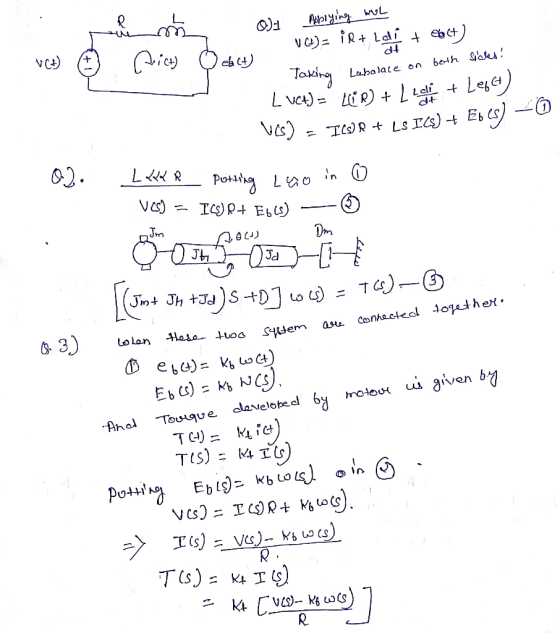
u(t) ta(t) e(t) A DC motor is a electro-mechanical system, where mechanical motor is coupled with...
 u(t) ta(t) e(t) A DC motor is a electro-mechanical system, where mechanical motor is coupled with an electrical circuit. The motor shows up in the circuit equation as a voltage loss proportional to the motor speed, and the electrical system shows up as the input torque proportional to the armatura current DC motor equations are given by dw(t) dialt) where J is the mass moment of inertia in kg-m2, b is the damping coefficient in N-m-s, K is the motor...
43 Questions 1. Using Figure 4-2, determine the electrical relationship characterizing a standard DC motor. Express...
 43 Questions 1. Using Figure 4-2, determine the electrical relationship characterizing a standard DC motor. Express the relationship in the Laplace domain. L. i,o, M ry Figure 4-2 DC Motor Electric Circuit 2. Determine and evaluate the motor electrical time constant, τ.. This is done by assuming that the shaft is stationary. You can find the parameters of the motor in Table B-1. 3. Assume τ. is negligible and simplify the motor electrical relationship determined in question 1. What is...
01- (08 Pts) Figure below is a diagram of a DC motor connected in parallel to...
 01- (08 Pts) Figure below is a diagram of a DC motor connected in parallel to a current source is the torque and back-EMF constants of the motor are K. K respectively, the motor resistance is R, also modeled as connected in parallel, the motor inertia is I. (not shown), and the motor inductance is negligible. The motor load is an inertia compliance (stiffness) K and viscous friction coefficient b, and it is attached to the motor via a gear...
1. Consider a schematic diagram of the permanent magnet brushed DC motor used in Quanser system...
 1. Consider a schematic diagram of the permanent magnet brushed DC motor used in Quanser system with two inertia loads (Jh and J4) and no viscous damping as shown in Fig. 2-1.. Since there is no gear system, motor shaft angular position and velocity, 0m, and wm, respectively, are equal to disc load angular position and velocity 0, and w, respectively. Derive electrical and mechanical differential equations describing this DC motor dynamics, as well as the relationship between motor torque...
 This assignment is for my Engr dynamics systems class.
Consider the electromechanical dynamic system shown in Figure 1(a). It consists of a cart of mass m moving without slipping on a linear ground track. The cart is equipped with an armature-controlled DC motor, which is coupled to a rack and pinion mechanism to convert the rotational motion to translation and to create the driving force for the system. Figure 1(b) shows the simplified equivalent electric circuit and the mechanical model...
This assignment is for my Engr dynamics systems class.
Consider the electromechanical dynamic system shown in Figure 1(a). It consists of a cart of mass m moving without slipping on a linear ground track. The cart is equipped with an armature-controlled DC motor, which is coupled to a rack and pinion mechanism to convert the rotational motion to translation and to create the driving force for the system. Figure 1(b) shows the simplified equivalent electric circuit and the mechanical model...
 Problem-5 (20 pts): Consider the DC servo motor shown in Figure-5. Assume that the input of the system is the applied armature voltage ea and the output is the load shaft position θ2. Assume also the following numerical values for the components: Ra-) Armature winding resistance = 0.2Ω La → Armature winding inductance = 0.1 mH Kb-) Back emf constant 0.05 Vs/rad K > Motor torque constant 0.06 Nm/A Jr Moment of inertia of the rotor of the motor =...
 Consider the system given below. The output is y(displacement from equilibrium position) and the input is V. (source voltage). The motor has an electrical constant Ke, a torque constant K, an armature inductance Lg and a resistance R. The rotor, shaft and disk together have inertia J and a viscous friction coefficient B. The disk has a radius ofr. (For the motor, assume that the torque is T = Ki,, and the back EMF is emf = KO). a. Derive...
 Show a sketch clearly labeling all of the voltages and
currents, and determine the governing differential equation as
indicated.
please show steps
6. The electro-mechanical system shown below consists of an electric motor with input voltage V which drives inertia I in the mechanical system (see torque T). Find the governing differential equations of motion for this electro-mechanical system in terms of the input voltage to the motor and output displacement y. Electrical System Vbas -Motor Motor Input Voltage bMotor...
Show a sketch clearly labeling all of the voltages and
currents, and determine the governing differential equation as
indicated.
please show steps
6. The electro-mechanical system shown below consists of an electric motor with input voltage V which drives inertia I in the mechanical system (see torque T). Find the governing differential equations of motion for this electro-mechanical system in terms of the input voltage to the motor and output displacement y. Electrical System Vbas -Motor Motor Input Voltage bMotor...
 The questions are at the bottom. I posted this previously
without the information at the top and the answer was missing some
key information.
Consider the electromechanical dynamic system shown in Figure 1(a). It consists of a cart of mass m moving without slipping on a linear ground track. The cart is equipped with an armature-controlled DC motor, which is coupled to a rack and pinion mechanism to convert the rotational motion to translation and to create the driving force...
The questions are at the bottom. I posted this previously
without the information at the top and the answer was missing some
key information.
Consider the electromechanical dynamic system shown in Figure 1(a). It consists of a cart of mass m moving without slipping on a linear ground track. The cart is equipped with an armature-controlled DC motor, which is coupled to a rack and pinion mechanism to convert the rotational motion to translation and to create the driving force...
 Q 1- 08 Pts) Figure below is a diagram of a DC motor connected in parnllel to a current source i,. The torque and back-EMF constants of the motor are Ko K respectively, the motor resistance is R, also modeled as connected in parallel, the motor inertia is 1- (not shown), and the motor inductance is negligible. The motor load is an inertia J with compliance (stiffness) K and viscous friction coefficient b, and it is attached a gear pair...
 u(t) ta(t) e(t) A DC motor is a electro-mechanical system, where mechanical motor is coupled with an electrical circuit. The motor shows up in the circuit equation as a voltage loss proportional to the motor speed, and the electrical system shows up as the input torque proportional to the armatura current DC motor equations are given by dw(t) dialt) where J is the mass moment of inertia in kg-m2, b is the damping coefficient in N-m-s, K is the motor...
 43 Questions 1. Using Figure 4-2, determine the electrical relationship characterizing a standard DC motor. Express the relationship in the Laplace domain. L. i,o, M ry Figure 4-2 DC Motor Electric Circuit 2. Determine and evaluate the motor electrical time constant, τ.. This is done by assuming that the shaft is stationary. You can find the parameters of the motor in Table B-1. 3. Assume τ. is negligible and simplify the motor electrical relationship determined in question 1. What is...
 01- (08 Pts) Figure below is a diagram of a DC motor connected in parallel to a current source is the torque and back-EMF constants of the motor are K. K respectively, the motor resistance is R, also modeled as connected in parallel, the motor inertia is I. (not shown), and the motor inductance is negligible. The motor load is an inertia compliance (stiffness) K and viscous friction coefficient b, and it is attached to the motor via a gear...
 1. Consider a schematic diagram of the permanent magnet brushed DC motor used in Quanser system with two inertia loads (Jh and J4) and no viscous damping as shown in Fig. 2-1.. Since there is no gear system, motor shaft angular position and velocity, 0m, and wm, respectively, are equal to disc load angular position and velocity 0, and w, respectively. Derive electrical and mechanical differential equations describing this DC motor dynamics, as well as the relationship between motor torque...
Most questions answered within 3 hours.
-
How do the mechanical features of bone affect its roles as
repositories of phosphate and calcium,...
asked 2 minutes ago -
P agreed to buy 100 barrels of widget oil, which was stored in a
large tank...
asked 2 minutes ago -
The unstable isotope 40K is used for dating rock samples. Its
half-life is 1.28×10⁹y. How many...
asked 5 minutes ago -
Compare and contrast constructed-response items and
selected-response items.
Identify at least one (1) advantage and one...
asked 6 minutes ago -
A) Find the moment of inertia of a 2 meter long stick with a
mass of...
asked 5 minutes ago -
For the code below write a public static main() method
in class Student that:
- creates...
asked 8 minutes ago -
Please show all steps. Thank you
A 1.0-cm-diameter pipe widens to 2.0 cm, then narrows to...
asked 20 minutes ago -
The equilibrium constant for the following reaction Ag+(aq) +
2NH3(aq) Ag(NH3)2+(aq) is K = 1.7 ×...
asked 29 minutes ago -
A carbon heater element has fixed resistance of 28 Ohms. It is
connected to an A/C...
asked 30 minutes ago -
Suppose X∼Exp(λ) for some λ >0. Compute E(X) and Var(X).
asked 44 minutes ago -
Xanth Co. has 8.9% annual coupon bonds with face value of $1,000
and 7 years remaining...
asked 41 minutes ago -
The Bellevue University bookstore purchases sweatshirts with the
school name and logo from a vendor. The...
asked 44 minutes ago