
The questions are at the bottom. I posted this previously without the information at the top and the answer was missing some key information.
Homework Answers


Add Answer to:
The questions are at the bottom. I posted this previously without the information at the top and ...
Consider the electromechanical dynamic system shown in Figure 1(a). It consists of a cart of mass...
 This assignment is for my Engr dynamics systems class.
Consider the electromechanical dynamic system shown in Figure 1(a). It consists of a cart of mass m moving without slipping on a linear ground track. The cart is equipped with an armature-controlled DC motor, which is coupled to a rack and pinion mechanism to convert the rotational motion to translation and to create the driving force for the system. Figure 1(b) shows the simplified equivalent electric circuit and the mechanical model...
This assignment is for my Engr dynamics systems class.
Consider the electromechanical dynamic system shown in Figure 1(a). It consists of a cart of mass m moving without slipping on a linear ground track. The cart is equipped with an armature-controlled DC motor, which is coupled to a rack and pinion mechanism to convert the rotational motion to translation and to create the driving force for the system. Figure 1(b) shows the simplified equivalent electric circuit and the mechanical model...
Consider the DC motor-driven wheeled mobile robot shown in figure, in which m is the mass...
Consider the DC motor-driven wheeled mobile robot shown in figure, in which m is the mass of the wheeled mobile robot, r is the radius of the driving wheel, and T is the torque delivered to the wheeled mobile robot by the DC motor. For simplicity, the motion is restricted to one spatial dimension. The figure also shows the simplified drive system, including the equivalent electrical circuit of the DC motor, the gears, and the driving wheel. The motor parameter...
Question 3: DC motors can be simplistically modeled as shown in Figure 5 MoTor back emf Vi: +1 Re...
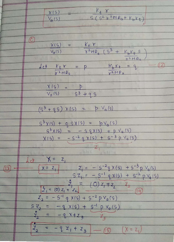
 Question 3: DC motors can be simplistically modeled as shown in Figure 5 MoTor back emf Vi: +1 Resistor Ra Ia Figure 5: Simplified model of DC Motor (a) Write the three characteristic equations that determine the behavior of the DC motor. Denote torque constant and speed constant as Ka, K, respectively. (b) Motor parameters are the quantities that define the behavior of the motor. List the motor parameters from the described model. What are their units? (c) For given...
Q 1- 08 Pts) Figure below is a diagram of a DC motor connected in parnllel to a current source i,...
 Q 1- 08 Pts) Figure below is a diagram of a DC motor connected in parnllel to a current source i,. The torque and back-EMF constants of the motor are Ko K respectively, the motor resistance is R, also modeled as connected in parallel, the motor inertia is 1- (not shown), and the motor inductance is negligible. The motor load is an inertia J with compliance (stiffness) K and viscous friction coefficient b, and it is attached a gear pair...
1) The following schematic is a model for a rack and pinion positioning system. The mass of the pinion gear is assumed...
 1) The following schematic is a model for a rack and pinion positioning system. The mass of the pinion gear is assumed to be negligible relative to that of the rack. The input to the system is an applied torque (e.g., from a DC motor), and the output is the position of the rack. k b (1)u1 m a) Derive the state-space model for the system. Your final model should be in terms of the physical system parameters (i.e., Tin(t),...
3.2 Pre-Lab Assignment When deriving the governing equations for an electromechanical system, it is often beneficial...
 3.2 Pre-Lab Assignment When deriving the governing equations for an electromechanical system, it is often beneficial to examine the electrical and mechanical components independently. Looking at only the electrical components of the QUBE-Servo DC motor (as shown in Figure 3.2): R v00 C e, (00 Figure 3.2: Electrical curcuit of the QUBE-Servo DC motor Q1. Write the differential equation in the form of Kirchoff's voltage law) in the Laplace domain for the electrical circuit (do not use parameter values given...
Otor shown below is controlled by the armature voltage va and load torque ease i ngular velocity ...
 otor shown below is controlled by the armature voltage va and load torque ease i ngular velocity w, and ts is the back-emf generated by op a model (first order differential equation) of armature current i in terms velop a model (irst order differential equation) of motor output speed w in terms ta and w as state variables, and va and Ti as inputs, write the state equations the motor. complete the following of motor output speed w and input...
i want to get part c,d The figure below is a gear-train mechanical system driven by...
 i want to get part c,d
The figure below is a gear-train mechanical system driven by a prescribed motion in the form of an angular displacement y(t). The motion is caused by an applied torque T(t) generated by a motor. The mass moment of inertias of the motor and the driving gear are J and J, respectively, whereas the mass moment of inertias of the load and the driven gear are J, and J2, respectively. The radii and angular displacements...
i want to get part c,d
The figure below is a gear-train mechanical system driven by a prescribed motion in the form of an angular displacement y(t). The motion is caused by an applied torque T(t) generated by a motor. The mass moment of inertias of the motor and the driving gear are J and J, respectively, whereas the mass moment of inertias of the load and the driven gear are J, and J2, respectively. The radii and angular displacements...
01- (08 Pts) Figure below is a diagram of a DC motor connected in parallel to...
 01- (08 Pts) Figure below is a diagram of a DC motor connected in parallel to a current source is the torque and back-EMF constants of the motor are K. K respectively, the motor resistance is R, also modeled as connected in parallel, the motor inertia is I. (not shown), and the motor inductance is negligible. The motor load is an inertia compliance (stiffness) K and viscous friction coefficient b, and it is attached to the motor via a gear...
2. (20 points) A field controlled DC motor model is given below where eaſt) is an...
 2. (20 points) A field controlled DC motor model is given below where eaſt) is an applied input voltage, ia(t) is the armature current, Ra and La are the armature resistance and inductance, respectively, e(t) is a back (or counter) emf (electro-motive force) le (t) = K w here K is a motor (torque) constant, t(t) is the torque generated by the motor, w(t) is the angular velocity, 0(t) is the angular position, J represents the rotor inertia and load...
 This assignment is for my Engr dynamics systems class.
Consider the electromechanical dynamic system shown in Figure 1(a). It consists of a cart of mass m moving without slipping on a linear ground track. The cart is equipped with an armature-controlled DC motor, which is coupled to a rack and pinion mechanism to convert the rotational motion to translation and to create the driving force for the system. Figure 1(b) shows the simplified equivalent electric circuit and the mechanical model...
This assignment is for my Engr dynamics systems class.
Consider the electromechanical dynamic system shown in Figure 1(a). It consists of a cart of mass m moving without slipping on a linear ground track. The cart is equipped with an armature-controlled DC motor, which is coupled to a rack and pinion mechanism to convert the rotational motion to translation and to create the driving force for the system. Figure 1(b) shows the simplified equivalent electric circuit and the mechanical model...
 Question 3: DC motors can be simplistically modeled as shown in Figure 5 MoTor back emf Vi: +1 Resistor Ra Ia Figure 5: Simplified model of DC Motor (a) Write the three characteristic equations that determine the behavior of the DC motor. Denote torque constant and speed constant as Ka, K, respectively. (b) Motor parameters are the quantities that define the behavior of the motor. List the motor parameters from the described model. What are their units? (c) For given...
 Q 1- 08 Pts) Figure below is a diagram of a DC motor connected in parnllel to a current source i,. The torque and back-EMF constants of the motor are Ko K respectively, the motor resistance is R, also modeled as connected in parallel, the motor inertia is 1- (not shown), and the motor inductance is negligible. The motor load is an inertia J with compliance (stiffness) K and viscous friction coefficient b, and it is attached a gear pair...
 1) The following schematic is a model for a rack and pinion positioning system. The mass of the pinion gear is assumed to be negligible relative to that of the rack. The input to the system is an applied torque (e.g., from a DC motor), and the output is the position of the rack. k b (1)u1 m a) Derive the state-space model for the system. Your final model should be in terms of the physical system parameters (i.e., Tin(t),...
 3.2 Pre-Lab Assignment When deriving the governing equations for an electromechanical system, it is often beneficial to examine the electrical and mechanical components independently. Looking at only the electrical components of the QUBE-Servo DC motor (as shown in Figure 3.2): R v00 C e, (00 Figure 3.2: Electrical curcuit of the QUBE-Servo DC motor Q1. Write the differential equation in the form of Kirchoff's voltage law) in the Laplace domain for the electrical circuit (do not use parameter values given...
 otor shown below is controlled by the armature voltage va and load torque ease i ngular velocity w, and ts is the back-emf generated by op a model (first order differential equation) of armature current i in terms velop a model (irst order differential equation) of motor output speed w in terms ta and w as state variables, and va and Ti as inputs, write the state equations the motor. complete the following of motor output speed w and input...
 i want to get part c,d
The figure below is a gear-train mechanical system driven by a prescribed motion in the form of an angular displacement y(t). The motion is caused by an applied torque T(t) generated by a motor. The mass moment of inertias of the motor and the driving gear are J and J, respectively, whereas the mass moment of inertias of the load and the driven gear are J, and J2, respectively. The radii and angular displacements...
i want to get part c,d
The figure below is a gear-train mechanical system driven by a prescribed motion in the form of an angular displacement y(t). The motion is caused by an applied torque T(t) generated by a motor. The mass moment of inertias of the motor and the driving gear are J and J, respectively, whereas the mass moment of inertias of the load and the driven gear are J, and J2, respectively. The radii and angular displacements...
 01- (08 Pts) Figure below is a diagram of a DC motor connected in parallel to a current source is the torque and back-EMF constants of the motor are K. K respectively, the motor resistance is R, also modeled as connected in parallel, the motor inertia is I. (not shown), and the motor inductance is negligible. The motor load is an inertia compliance (stiffness) K and viscous friction coefficient b, and it is attached to the motor via a gear...
 2. (20 points) A field controlled DC motor model is given below where eaſt) is an applied input voltage, ia(t) is the armature current, Ra and La are the armature resistance and inductance, respectively, e(t) is a back (or counter) emf (electro-motive force) le (t) = K w here K is a motor (torque) constant, t(t) is the torque generated by the motor, w(t) is the angular velocity, 0(t) is the angular position, J represents the rotor inertia and load...
Most questions answered within 3 hours.
-
The following results were obtained as
part of a multiple regression analysis involving 3 independent
variables:...
asked 45 minutes ago -
The time to complete a standardized exam is approximately normal
with a mean of 70 minutes...
asked 2 hours ago -
Two thousand randomly selected adults were asked whether or not
they have ever shopped on the...
asked 2 hours ago -
Estimate the diffusion coefficient for methyl phenyl sulfide in
water at 25 degrees Celcius.
asked 2 hours ago -
10.g of a certain metal absorb 40. cal of heat and the temperature
is abserved to...
asked 3 hours ago -
How many milliliters of 0.0695 M Ca( OH)
2would be required to exactly neutralize 176 mL...
asked 3 hours ago -
A telephone survey uses a random digit dialing machine to call
subjects. The random digit dialing...
asked 4 hours ago -
How can having too little or too much of a certain
protein cause problems for an...
asked 5 hours ago -
Assume a muscle has a PCSA = 20 cm2 and Lo = 12 cm. Assume it...
asked 7 hours ago -
What is the yield to maturity of a ten-year, $1,000 bond with a
5.2% coupon rate...
asked 7 hours ago -
A mass m = 5 kg is tied on one end of a rope and is...
asked 7 hours ago -
The Average sales price of single-family houses in Charlotte is
$210,000 with a standard deviation of...
asked 8 hours ago