
Homework Answers


Add Answer to:
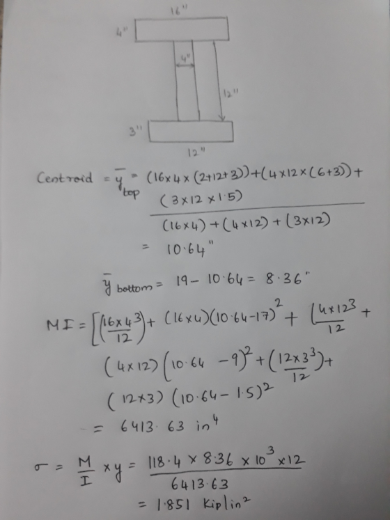
1- For the beam shown below find: a) The maximum normal stresses due to bending b)...
Problem 1. Consider the beam cross sections shown in figures (a) and (b). If the material...
 Problem 1. Consider the beam cross sections shown in figures (a) and (b). If the material comprising beams with these cross sections has allowable bending stress Allow = 25000 psi, either in tension or compression, determine the maximum bending moment each beam can carry. Assume elastic behavior. Take D=6 in. Problem 2. The beam shown has the cross-section indicated. Indicate the location along the beam where the maximum and minimum normal stresses occur in the beam. Determine the values of...
For the beam and loading shown, determine: A. The maximum shearing force in the beam =...
 For the beam and loading shown, determine:
A. The maximum shearing force in the beam = kips
B. The maximum bending moment in the beam = kip in
C. The centroid of the cross section is at (in.) from the bottom
b
D. The moment of inertia of the cross section = in^4
E.the shearing stress at point a = ksi
F. The shearing stress at point b = ksi
G. The max shearing stress in the cross section =...
For the beam and loading shown, determine:
A. The maximum shearing force in the beam = kips
B. The maximum bending moment in the beam = kip in
C. The centroid of the cross section is at (in.) from the bottom
b
D. The moment of inertia of the cross section = in^4
E.the shearing stress at point a = ksi
F. The shearing stress at point b = ksi
G. The max shearing stress in the cross section =...
Blem 2. (70 points) 1. For the beam shown in Figure (a): a) b) draw the shear force and bending m...
 blem 2. (70 points) 1. For the beam shown in Figure (a): a) b) draw the shear force and bending moment diagrams. (30 points) Select the most economical W shape for the beam with an allowable bending stress of 30 ksi. (10 points) determine the maximum tensile and compressive bending stresses at any location along the beam if the section shown in Figure (b) is used instead of the W shape section selectedin Part b. Would the beam be safe...
a. Determine the maximum tensile and compressive bending stresses associated with the maximum positive moment. b. Determine the maximum tensile and compressive bending stresses associated with the ma...
 a. Determine the maximum tensile and compressive bending
stresses associated with the maximum positive moment.b. Determine the maximum tensile and compressive bending
stresses associated with the maximum negative moment.c. Determine the absolute maximum tensile stress in the beam and
the location.d. Determine the absolute maximum compressive stress in the beam
and the location.e. Determine the maximum shear stress associated with maximum
positive shear force.f. Determine the maximum shear stress associated with maximum
negative shear force.g. Determine the absolute maximum shear...
a. Determine the maximum tensile and compressive bending
stresses associated with the maximum positive moment.b. Determine the maximum tensile and compressive bending
stresses associated with the maximum negative moment.c. Determine the absolute maximum tensile stress in the beam and
the location.d. Determine the absolute maximum compressive stress in the beam
and the location.e. Determine the maximum shear stress associated with maximum
positive shear force.f. Determine the maximum shear stress associated with maximum
negative shear force.g. Determine the absolute maximum shear...
The beam shown below is subjected to a uniform load of 2 kips/ft, two concentrated transverse...
 The beam shown below is subjected to a uniform load of 2 kips/ft, two concentrated transverse loads of 12 kips, and 6 kips, and a tensile axial force of 10 kips. a) Draw the shear and moment diagrams. (8) b) Find the stresses at B. (10) c) Find the maximum shearing stress in the beam. (10) 12 kips 2 k/ft 6 kips 10 kips 4 41 8' A B D E 12" 2" 2 14" B 24 16"
12.19 and 12.20 Draw the shear and bending-moment diagrams for the beam and loading shown, and...
 12.19 and 12.20 Draw the shear and bending-moment diagrams for the beam and loading shown, and determine the maximum normal stress due to bending 25 kips 25 kips 25 kips 'c D Ε A S12 x 35 6 ft 1 ft 2 ft 2 ft Fig. P12.19
Learning Goal: The beam shown (Figure 1) is supported by a pin at A and a...
 Learning Goal: The beam shown (Figure 1) is supported by a pin at A and a cable at B. Two loads P = 18 kN are applied straight down from the centerline of the bottom face. Determine the state of stress at the point shown (Figure 2) in a section 2 m from the wall. The dimensions are w = 5.4 cm , h = 12 cm, L = 0.8 m, a = 1.5 cm , and b = 4...
Problem 05.154.b - Determine the normal stress at C Determine the corresponding maximum normal st...
 Problem 05.154.b -
Determine the normal stress at C
Determine the
corresponding maximum normal stress due to bending. (Round the
final answer to two decimal places.)
The corresponding
maximum normal stress is _____ ksi.
Problem 05.154 - Determine the distance a that results in the smallest bending moment and the correcting normal stress Consider the given beam and loading, where P 21 kips. Take the section modulus as 1.67 in P kips o.S kips 1.2 kips C D S3 x...
Problem 05.154.b -
Determine the normal stress at C
Determine the
corresponding maximum normal stress due to bending. (Round the
final answer to two decimal places.)
The corresponding
maximum normal stress is _____ ksi.
Problem 05.154 - Determine the distance a that results in the smallest bending moment and the correcting normal stress Consider the given beam and loading, where P 21 kips. Take the section modulus as 1.67 in P kips o.S kips 1.2 kips C D S3 x...
(a) Determine the maximum compressive and tensile normal stresses in the A-36 structural steel beam shown...
 (a) Determine the maximum compressive and tensile normal
stresses in the A-36 structural steel beam shown and define their
locations (location along the beam and on the cross section). (b)
Determine the deflection of point B using the double
integration method. The height of the cross section shown (in the
y-direction) is 5 inches and width (in the
z-direction) is 10 inches, and the average thickness
throughout is 0.5 inches. (Use elastic properties for all
calculations)
ANSWER: (a) max tensile...
(a) Determine the maximum compressive and tensile normal
stresses in the A-36 structural steel beam shown and define their
locations (location along the beam and on the cross section). (b)
Determine the deflection of point B using the double
integration method. The height of the cross section shown (in the
y-direction) is 5 inches and width (in the
z-direction) is 10 inches, and the average thickness
throughout is 0.5 inches. (Use elastic properties for all
calculations)
ANSWER: (a) max tensile...
For the beam shown, a) Draw the bending moment diagram, b) Determine the maximum normal stress...
 For the beam shown, a) Draw the bending moment diagram, b)
Determine the maximum normal stress due to bending.
For the beam shown, a) Draw the bending moment diagram, b) Determine the maximum normal stress due to bending. 300 N 400 N/m D B 200 N.m с Hinge 2.00 m 2.00 m + 2.00 m 300 mm N А 750 mm x = 292 mm 560 mm NA: Neutral Axis
For the beam shown, a) Draw the bending moment diagram, b)
Determine the maximum normal stress due to bending.
For the beam shown, a) Draw the bending moment diagram, b) Determine the maximum normal stress due to bending. 300 N 400 N/m D B 200 N.m с Hinge 2.00 m 2.00 m + 2.00 m 300 mm N А 750 mm x = 292 mm 560 mm NA: Neutral Axis
 Problem 1. Consider the beam cross sections shown in figures (a) and (b). If the material comprising beams with these cross sections has allowable bending stress Allow = 25000 psi, either in tension or compression, determine the maximum bending moment each beam can carry. Assume elastic behavior. Take D=6 in. Problem 2. The beam shown has the cross-section indicated. Indicate the location along the beam where the maximum and minimum normal stresses occur in the beam. Determine the values of...
 For the beam and loading shown, determine:
A. The maximum shearing force in the beam = kips
B. The maximum bending moment in the beam = kip in
C. The centroid of the cross section is at (in.) from the bottom
b
D. The moment of inertia of the cross section = in^4
E.the shearing stress at point a = ksi
F. The shearing stress at point b = ksi
G. The max shearing stress in the cross section =...
For the beam and loading shown, determine:
A. The maximum shearing force in the beam = kips
B. The maximum bending moment in the beam = kip in
C. The centroid of the cross section is at (in.) from the bottom
b
D. The moment of inertia of the cross section = in^4
E.the shearing stress at point a = ksi
F. The shearing stress at point b = ksi
G. The max shearing stress in the cross section =...
 blem 2. (70 points) 1. For the beam shown in Figure (a): a) b) draw the shear force and bending moment diagrams. (30 points) Select the most economical W shape for the beam with an allowable bending stress of 30 ksi. (10 points) determine the maximum tensile and compressive bending stresses at any location along the beam if the section shown in Figure (b) is used instead of the W shape section selectedin Part b. Would the beam be safe...
 a. Determine the maximum tensile and compressive bending
stresses associated with the maximum positive moment.b. Determine the maximum tensile and compressive bending
stresses associated with the maximum negative moment.c. Determine the absolute maximum tensile stress in the beam and
the location.d. Determine the absolute maximum compressive stress in the beam
and the location.e. Determine the maximum shear stress associated with maximum
positive shear force.f. Determine the maximum shear stress associated with maximum
negative shear force.g. Determine the absolute maximum shear...
a. Determine the maximum tensile and compressive bending
stresses associated with the maximum positive moment.b. Determine the maximum tensile and compressive bending
stresses associated with the maximum negative moment.c. Determine the absolute maximum tensile stress in the beam and
the location.d. Determine the absolute maximum compressive stress in the beam
and the location.e. Determine the maximum shear stress associated with maximum
positive shear force.f. Determine the maximum shear stress associated with maximum
negative shear force.g. Determine the absolute maximum shear...
 The beam shown below is subjected to a uniform load of 2 kips/ft, two concentrated transverse loads of 12 kips, and 6 kips, and a tensile axial force of 10 kips. a) Draw the shear and moment diagrams. (8) b) Find the stresses at B. (10) c) Find the maximum shearing stress in the beam. (10) 12 kips 2 k/ft 6 kips 10 kips 4 41 8' A B D E 12" 2" 2 14" B 24 16"
 12.19 and 12.20 Draw the shear and bending-moment diagrams for the beam and loading shown, and determine the maximum normal stress due to bending 25 kips 25 kips 25 kips 'c D Ε A S12 x 35 6 ft 1 ft 2 ft 2 ft Fig. P12.19
 Learning Goal: The beam shown (Figure 1) is supported by a pin at A and a cable at B. Two loads P = 18 kN are applied straight down from the centerline of the bottom face. Determine the state of stress at the point shown (Figure 2) in a section 2 m from the wall. The dimensions are w = 5.4 cm , h = 12 cm, L = 0.8 m, a = 1.5 cm , and b = 4...
 Problem 05.154.b -
Determine the normal stress at C
Determine the
corresponding maximum normal stress due to bending. (Round the
final answer to two decimal places.)
The corresponding
maximum normal stress is _____ ksi.
Problem 05.154 - Determine the distance a that results in the smallest bending moment and the correcting normal stress Consider the given beam and loading, where P 21 kips. Take the section modulus as 1.67 in P kips o.S kips 1.2 kips C D S3 x...
Problem 05.154.b -
Determine the normal stress at C
Determine the
corresponding maximum normal stress due to bending. (Round the
final answer to two decimal places.)
The corresponding
maximum normal stress is _____ ksi.
Problem 05.154 - Determine the distance a that results in the smallest bending moment and the correcting normal stress Consider the given beam and loading, where P 21 kips. Take the section modulus as 1.67 in P kips o.S kips 1.2 kips C D S3 x...
 (a) Determine the maximum compressive and tensile normal
stresses in the A-36 structural steel beam shown and define their
locations (location along the beam and on the cross section). (b)
Determine the deflection of point B using the double
integration method. The height of the cross section shown (in the
y-direction) is 5 inches and width (in the
z-direction) is 10 inches, and the average thickness
throughout is 0.5 inches. (Use elastic properties for all
calculations)
ANSWER: (a) max tensile...
(a) Determine the maximum compressive and tensile normal
stresses in the A-36 structural steel beam shown and define their
locations (location along the beam and on the cross section). (b)
Determine the deflection of point B using the double
integration method. The height of the cross section shown (in the
y-direction) is 5 inches and width (in the
z-direction) is 10 inches, and the average thickness
throughout is 0.5 inches. (Use elastic properties for all
calculations)
ANSWER: (a) max tensile...
 For the beam shown, a) Draw the bending moment diagram, b)
Determine the maximum normal stress due to bending.
For the beam shown, a) Draw the bending moment diagram, b) Determine the maximum normal stress due to bending. 300 N 400 N/m D B 200 N.m с Hinge 2.00 m 2.00 m + 2.00 m 300 mm N А 750 mm x = 292 mm 560 mm NA: Neutral Axis
For the beam shown, a) Draw the bending moment diagram, b)
Determine the maximum normal stress due to bending.
For the beam shown, a) Draw the bending moment diagram, b) Determine the maximum normal stress due to bending. 300 N 400 N/m D B 200 N.m с Hinge 2.00 m 2.00 m + 2.00 m 300 mm N А 750 mm x = 292 mm 560 mm NA: Neutral Axis
Most questions answered within 3 hours.
-
At the beginning of the period, the Fabricating Department
budgeted direct labor of $136,500 and equipment...
asked 7 minutes ago -
Please answer all
____ 28. Rent control is usually
justified on the grounds that it protects...
asked 7 minutes ago -
PARTS A-D HAVE BEEN ANSWERED. WAS TOLD TO REPOST. ONLY ANSWER
PARTS E and F.
A...
asked 25 minutes ago -
2) You are given the task of finding a representation for a
circle in a drawing...
asked 1 hour ago -
STUDY QUESTION: Does use of diet drug fen-phen
(fenfluramine-phentermine) cause valvular heart disease?
HINT: Valvular heart...
asked 1 hour ago -
1. An object weighing 40 N rests on a surface. The coefficient
of friction is 0.35....
asked 2 hours ago -
Investor company owns 35% of investee company voting stock and
accounts for the investment under the...
asked 3 hours ago -
The number of major faults on a randomly chosen 1 km stretch of
highway has a...
asked 4 hours ago -
Consider the competitive environment of Starbuck's, Progressive
Insurance, a manufacturing firm with low turnover, or a...
asked 4 hours ago -
3. Gains from trade
Consider two neighbouring island countries called Euphoria and
Contente. They each have...
asked 6 hours ago -
A business executive has the option to invest money in two
plans: Plan A guarantees that...
asked 9 hours ago -
Hello, can someone please help me answer this question?
How much heat is absorbed by a...
asked 9 hours ago