A. Design a circuit using D flip-flops that will generate the sequence 0, 0, 1, 0,...
A. Design a circuit using D flip-flops that will generate the sequence 0, 0, 1, 0, 1, 1 and repeat. Do this by designing a counter for any sequence of states such that the first flip-flop takes on this sequence. There are many correct answers, but do not duplicate states, because each state can have only one next state.
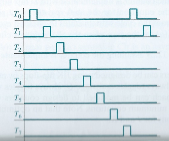
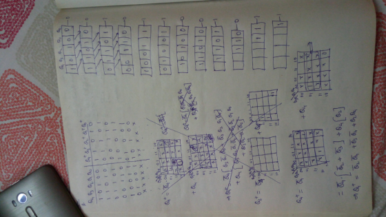
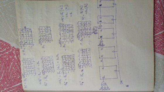
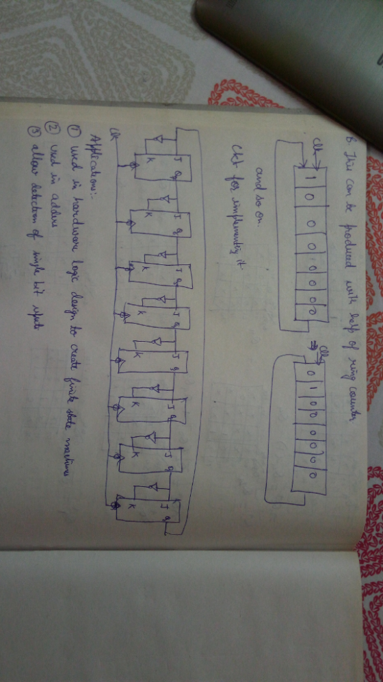
B. A pulse-generating circuit generates eight repetitive pulses as shown in the figure. Implement the pulse-generating circuit using a binary counter circuit and a minimum of gate logic. Use J-k flip-flops for the counters that trigger on the falling edge of a clock that has a frequency eight times the frequency of one of the pulses. Research real-world systems that use this type of pulse-generating circuit. List as many systems as you can with a brief description of why they use pulsed signals.
Homework Answers
Add Answer to:
A. Design a circuit using D flip-flops that will generate the
sequence 0, 0, 1, 0,...
A pulse-generating circuit generates eight repetitive pulses as shown in the figure. Implement the pulse-generating circuit using the counter circuits listed and a minimum of gate logic. Use J-K flip...
 A pulse-generating circuit generates eight repetitive pulses as shown in the figure. Implement the pulse-generating circuit using the counter circuits listed and a minimum of gate logic. Use J-K flip-flops for the counters that trigger on the falling edge of a clock that has a frequency eight times the frequency of one of the pulses. The pulses must be free of glitches; explain any restrictions on the propagation delays of gates and flip-flops so that the pulses will be glitch...
Design a 5-bit binary counter using JK flip flops. Draw the flip-flop circuit diagram, the state...
Design a 5-bit binary counter using JK flip flops. Draw the flip-flop circuit diagram, the state graph, the timing diagram, the truth table (with clk pulse) and the state table (with present and next states).
6. (20') Asynchronous Counters (Please show all your steps.) (a) How many Flip-flops are required to...
 6. (20') Asynchronous Counters (Please show all your steps.) (a) How many Flip-flops are required to build a binary counter that counts from 0 to 63? (b) Determine the frequency at the output of the last Flip-flop of this counter for an input clock frequency of 256 KHz. (C) If the counter is initially at zero, what count will it hold after 68 pulses? (d) Suppose the counter was designed to be an asynchronous/ripple counter. Determine the maximum input clock...
Using D flip-flops, design a Moore circuit that detects the sequence 1100. The circuit outputs I...
 Using D flip-flops, design a Moore circuit that detects the sequence 1100. The circuit outputs I when the sequence 1100 is received and outputs 0 otherwise. Draw the state diagram and state table, and find the D flip-flops input equations and the output equation x- Z Clock Hint: X: 01011 00011001100011 Z: 0 0 0 0 0 0 100000000000
TIMING Consider the following ciru. The clock connections to the flip-flops are not shown (both flip-flops...
 TIMING Consider the following ciru. The clock connections to the flip-flops are not shown (both flip-flops are clocked by the same clock). Y1 D a Assume the following Delay of each AND gate: 1 ns Delay of each inverter 04 ns Set up time of each flip-flop: 0.1 ns Hold time of each flip-flop: 0 ns Clk-to-Q delay of each fip-flop: 0.3 ns a) What is the maximum frequency of the clock in this cicuit (in MHz)? b) Suppose the...
Up-Down counter with enable using JK flip-flops: Design, construct and test a 2-bit counter that counts up or down.
Up-Down counter with enable using JK flip-flops: Design, construct and test a 2-bit counter that counts up or down. An enable input E determines whether the counter is on or off. If E = 0, the counter is disabled and remains in the present count even though clock pulses are applied to the flip-flops. If E= 1, the counter in enabled and a second input, x, determines the count direction. If x= 1, the circuit counts up with the sequence...
Done 01. When an inverter is placed between both inputs of an SR. flip-lop, the resulting flip-fo...
 digital system solve Q3andQ4
Done 01. When an inverter is placed between both inputs of an SR. flip-lop, the resulting flip-fop is a (a) JK flip-flop (b) T flip-lop (c) Master Slave JK flip-flop (d) D flip-flop 02. A D flip-flop utilizing a Positive-Giate-Triggered (PGT) Clock is in the CLEAR" stae Which of the following input actions will cause it to change states? NGT stands for Negative-Gate-Triggered (a) CLOCK-NGT, D-O (b) CLOCK-PGT, D- (c) CLOCK- NGT: D- (d) CLOCK- PGT,...
digital system solve Q3andQ4
Done 01. When an inverter is placed between both inputs of an SR. flip-lop, the resulting flip-fop is a (a) JK flip-flop (b) T flip-lop (c) Master Slave JK flip-flop (d) D flip-flop 02. A D flip-flop utilizing a Positive-Giate-Triggered (PGT) Clock is in the CLEAR" stae Which of the following input actions will cause it to change states? NGT stands for Negative-Gate-Triggered (a) CLOCK-NGT, D-O (b) CLOCK-PGT, D- (c) CLOCK- NGT: D- (d) CLOCK- PGT,...
In Verilog, design the circuit below (an upcounter) using 3 D flip flops shown in image2....
 In Verilog, design the circuit below (an upcounter) using 3 D
flip flops shown in image2. To be programmed in Vivado and used on
BASYS3 board
REG3 DO 20 QO DI 01 21 XORZ AND2 D2 Q2 Q2 XORZ cik clock D[2] D[11 DIO D Flip-Flop Flip Flop swin en sw in sw_in clock clock clock 0[2] [11 Q[o]
In Verilog, design the circuit below (an upcounter) using 3 D
flip flops shown in image2. To be programmed in Vivado and used on
BASYS3 board
REG3 DO 20 QO DI 01 21 XORZ AND2 D2 Q2 Q2 XORZ cik clock D[2] D[11 DIO D Flip-Flop Flip Flop swin en sw in sw_in clock clock clock 0[2] [11 Q[o]
Design a counter circuit with sequence 0, 1, 2, …, 11 and repeat using JK flip-flops....
Design a counter circuit with sequence 0, 1, 2, …, 11 and repeat using JK flip-flops. Design the circuit with pen and paper and then simulate it using Logisim (justify the input values chosen)
All flip flops are positive-edge triggered. Assume each flip flop starts at 0.
 All flip flops are
positive-edge triggered. Assume each flip flop starts at 0.
Problem 11: (8 pts) For the following circuit, complete the timing diagram for the state of each flip flop and the output, where shown. All flip flops are positive-edge triggered. Assume each flip flop starts at 0. J-K FF TFF CLK PRE CLR PRE CLR CLR回 Clock CLR
Problem 11: (8 pts) For the following circuit, complete the timing diagram for the state of each flip flop...
All flip flops are
positive-edge triggered. Assume each flip flop starts at 0.
Problem 11: (8 pts) For the following circuit, complete the timing diagram for the state of each flip flop and the output, where shown. All flip flops are positive-edge triggered. Assume each flip flop starts at 0. J-K FF TFF CLK PRE CLR PRE CLR CLR回 Clock CLR
Problem 11: (8 pts) For the following circuit, complete the timing diagram for the state of each flip flop...
 A pulse-generating circuit generates eight repetitive pulses as shown in the figure. Implement the pulse-generating circuit using the counter circuits listed and a minimum of gate logic. Use J-K flip-flops for the counters that trigger on the falling edge of a clock that has a frequency eight times the frequency of one of the pulses. The pulses must be free of glitches; explain any restrictions on the propagation delays of gates and flip-flops so that the pulses will be glitch...
 6. (20') Asynchronous Counters (Please show all your steps.) (a) How many Flip-flops are required to build a binary counter that counts from 0 to 63? (b) Determine the frequency at the output of the last Flip-flop of this counter for an input clock frequency of 256 KHz. (C) If the counter is initially at zero, what count will it hold after 68 pulses? (d) Suppose the counter was designed to be an asynchronous/ripple counter. Determine the maximum input clock...
 Using D flip-flops, design a Moore circuit that detects the sequence 1100. The circuit outputs I when the sequence 1100 is received and outputs 0 otherwise. Draw the state diagram and state table, and find the D flip-flops input equations and the output equation x- Z Clock Hint: X: 01011 00011001100011 Z: 0 0 0 0 0 0 100000000000
 TIMING Consider the following ciru. The clock connections to the flip-flops are not shown (both flip-flops are clocked by the same clock). Y1 D a Assume the following Delay of each AND gate: 1 ns Delay of each inverter 04 ns Set up time of each flip-flop: 0.1 ns Hold time of each flip-flop: 0 ns Clk-to-Q delay of each fip-flop: 0.3 ns a) What is the maximum frequency of the clock in this cicuit (in MHz)? b) Suppose the...
 digital system solve Q3andQ4
Done 01. When an inverter is placed between both inputs of an SR. flip-lop, the resulting flip-fop is a (a) JK flip-flop (b) T flip-lop (c) Master Slave JK flip-flop (d) D flip-flop 02. A D flip-flop utilizing a Positive-Giate-Triggered (PGT) Clock is in the CLEAR" stae Which of the following input actions will cause it to change states? NGT stands for Negative-Gate-Triggered (a) CLOCK-NGT, D-O (b) CLOCK-PGT, D- (c) CLOCK- NGT: D- (d) CLOCK- PGT,...
digital system solve Q3andQ4
Done 01. When an inverter is placed between both inputs of an SR. flip-lop, the resulting flip-fop is a (a) JK flip-flop (b) T flip-lop (c) Master Slave JK flip-flop (d) D flip-flop 02. A D flip-flop utilizing a Positive-Giate-Triggered (PGT) Clock is in the CLEAR" stae Which of the following input actions will cause it to change states? NGT stands for Negative-Gate-Triggered (a) CLOCK-NGT, D-O (b) CLOCK-PGT, D- (c) CLOCK- NGT: D- (d) CLOCK- PGT,...
 In Verilog, design the circuit below (an upcounter) using 3 D
flip flops shown in image2. To be programmed in Vivado and used on
BASYS3 board
REG3 DO 20 QO DI 01 21 XORZ AND2 D2 Q2 Q2 XORZ cik clock D[2] D[11 DIO D Flip-Flop Flip Flop swin en sw in sw_in clock clock clock 0[2] [11 Q[o]
In Verilog, design the circuit below (an upcounter) using 3 D
flip flops shown in image2. To be programmed in Vivado and used on
BASYS3 board
REG3 DO 20 QO DI 01 21 XORZ AND2 D2 Q2 Q2 XORZ cik clock D[2] D[11 DIO D Flip-Flop Flip Flop swin en sw in sw_in clock clock clock 0[2] [11 Q[o]
 All flip flops are
positive-edge triggered. Assume each flip flop starts at 0.
Problem 11: (8 pts) For the following circuit, complete the timing diagram for the state of each flip flop and the output, where shown. All flip flops are positive-edge triggered. Assume each flip flop starts at 0. J-K FF TFF CLK PRE CLR PRE CLR CLR回 Clock CLR
Problem 11: (8 pts) For the following circuit, complete the timing diagram for the state of each flip flop...
All flip flops are
positive-edge triggered. Assume each flip flop starts at 0.
Problem 11: (8 pts) For the following circuit, complete the timing diagram for the state of each flip flop and the output, where shown. All flip flops are positive-edge triggered. Assume each flip flop starts at 0. J-K FF TFF CLK PRE CLR PRE CLR CLR回 Clock CLR
Problem 11: (8 pts) For the following circuit, complete the timing diagram for the state of each flip flop...
Most questions answered within 3 hours.
-
A gas occupies 200. mL in a piston. If the pressure of the
piston were decreased...
asked 4 minutes ago -
A fossil is found to have a 14C level of 71.0% compared to
living organisms. How...
asked 8 minutes ago -
Many communist or socialist countries have a department that
addresses public health as well as the...
asked 9 minutes ago -
the following questions are either true or false answers
1. The Central Limit Theorem allows one...
asked 10 minutes ago -
The patient recovery time from a particular surgical procedure
is normally distributed with a mean of...
asked 16 minutes ago -
Human relations refer to the way a company arranges people,
jobs, and communications so that work...
asked 33 minutes ago -
Python Program: Design the logic for and implement a program
that merges the two files into...
asked 31 minutes ago -
The specific radiocarbon activity of a sample of wood is 6.25
gms dpm/gm of carbon. The...
asked 36 minutes ago -
An aqueous magnesium chloride solution is made by dissolving
6.96 moles of MgCl2 in sufficient water...
asked 39 minutes ago -
Ken believes the average age of men who come to get a haircut at
his barber...
asked 1 hour ago -
(Ratio Analysis): Last year Co. XYZ had sales of $ 400,000, with
“cost of goods sold”...
asked 1 hour ago -
can someone please write the balanced chemical
equation for the synthesis of Bromoacetanilide
from;
aniline +...
asked 1 hour ago