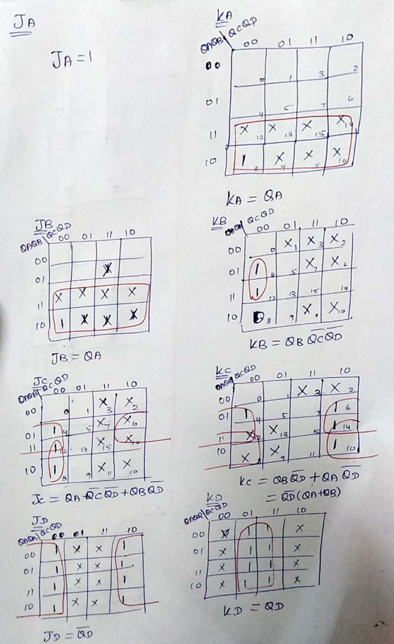
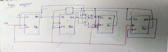
We need to design a four-bit binary synchronous down counter using JK flip-flop. I'd appreciate it...
We need to design a four-bit binary synchronous down counter using JK flip-flop. I'd appreciate it if you could draw the truth and logic.
Homework Answers


Add Answer to:
We need to design a four-bit binary synchronous down counter
using JK flip-flop. I'd appreciate it...
design 4-bit synchronous up counter using JK flip flop. show truth table, k-maps, and circuit digram...
design 4-bit synchronous up counter using JK flip flop. show truth table, k-maps, and circuit digram using logic gates.
Design a 5-bit binary counter using JK flip flops. Draw the flip-flop circuit diagram, the state...
Design a 5-bit binary counter using JK flip flops. Draw the flip-flop circuit diagram, the state graph, the timing diagram, the truth table (with clk pulse) and the state table (with present and next states).
1. Design a synchronous 2-bit up-down counter using a T flip flop for the most significant bit an...
 1. Design a synchronous 2-bit up-down counter using a T flip flop for the most significant bit and an SR flip flop for the least significant bit; when the input X-1, it should count down and for X-0, it should count up. Use SOP.
1. Design a synchronous 2-bit up-down counter using a T flip flop for the most significant bit and an SR flip flop for the least significant bit; when the input X-1, it should count down and...
1. Design a synchronous 2-bit up-down counter using a T flip flop for the most significant bit and an SR flip flop for the least significant bit; when the input X-1, it should count down and for X-0, it should count up. Use SOP.
1. Design a synchronous 2-bit up-down counter using a T flip flop for the most significant bit and an SR flip flop for the least significant bit; when the input X-1, it should count down and...
Design a synchronous 2-bit up-down counter using a SR flip flop for the most significant bit and an T flip flop for the least significant bit;
Design a synchronous 2-bit up-down counter using a SR flip flop for the most significant bit and an T flip flop for the least significant bit; when the input X=0, it should count down and for X=1, it should count up. Use SOP
I NEED HELP WITH FLIP FLOPS Flip-flop type JK Design a JK flip flop using only...
I NEED HELP WITH FLIP FLOPS Flip-flop type JK Design a JK flip flop using only logic gates .Fill the truth table exercising all possible combinations of inputs for J and K Flip-flop type D Set the JK type flip flop from the previous step to work as a flip flop type D. Fill the truth table by exercising all combinations of possible entries D Flip-flop type T Set the circuit of the previous step to work as a flip...
Need a schematic for a 4 bit synchronous up/down counter using two JK flip flops (74112)...
Need a schematic for a 4 bit synchronous up/down counter using two JK flip flops (74112) with the program Quartus II. I am using version 14.1. There should be a preset, clear, and clock input. Four outputs. Please complete the schematic and take a screenshot for me. Has to successfully pass compilation, thank you!
Design a 4-bit binary up counter (like the following state diagram) using JK flip flops.
 Design a 4-bit binary up counter (like the following state diagram) using JK flip flops. State diagram. 0000 0001 11111 (a) Draw the state table with the input values for J K flip flops(b) Simplify the input equations by K map (c) Draw the logic diagram
Using Proteus, design Synchronous 4 bit Up binary counter using JK flip flops (Use 74HC76 JK flipflop). The circuit count from 0000 to 1111, etc.
 Q2) 4-bit Synchronous Counter Using Proteus, design Synchronous 4 bit Up binary counter using JK flip flops (Use 74HC76 JK flipflop). The circuit count from 0000 to 1111, etc. Experiment procedure: طريقة اجراء التجربة a) Complete the circuit. You can use external gates based on the following conditions: o Flipflop A switches every clock. o Flipflop B switches when the output of flipflop A=1 o Flipflop C switches when the outputs of A-B=1 o Flipflop D switches when the outputs of A=B=C=1 b) What is the typical feature of...
(b)(i) Using T flip-flop as main components, design a 3-bit synchronous counter that perform counting as...
 (b)(i) Using T flip-flop as main components, design a 3-bit synchronous counter that perform counting as the following sequence 0,2,4,6,1,3,5,7 then repeats (its sequence) [20 marks] (ii) Draw a complete circuit to show how the T flip-flops are interconnected and label it appropriately. Also show how the counter can be asynchronous reset. [5 marks] (iii) Draw a timing diagram for at least four clock cycles [8 marks)
a. Design a count up/count down counter that counts from 0 up to 4, then 4 down to 0 using D flip flop.
2. Synchronous Counters: a. Design a count up/count down counter that counts from 0 up to 4, then 4 down to 0 using D flip flop. b. Design a count up counter that counts from 0 up to 12 using JK flip flops.
 1. Design a synchronous 2-bit up-down counter using a T flip flop for the most significant bit and an SR flip flop for the least significant bit; when the input X-1, it should count down and for X-0, it should count up. Use SOP.
1. Design a synchronous 2-bit up-down counter using a T flip flop for the most significant bit and an SR flip flop for the least significant bit; when the input X-1, it should count down and...
1. Design a synchronous 2-bit up-down counter using a T flip flop for the most significant bit and an SR flip flop for the least significant bit; when the input X-1, it should count down and for X-0, it should count up. Use SOP.
1. Design a synchronous 2-bit up-down counter using a T flip flop for the most significant bit and an SR flip flop for the least significant bit; when the input X-1, it should count down and...
 (b)(i) Using T flip-flop as main components, design a 3-bit synchronous counter that perform counting as the following sequence 0,2,4,6,1,3,5,7 then repeats (its sequence) [20 marks] (ii) Draw a complete circuit to show how the T flip-flops are interconnected and label it appropriately. Also show how the counter can be asynchronous reset. [5 marks] (iii) Draw a timing diagram for at least four clock cycles [8 marks)
Most questions answered within 3 hours.
-
The average length of time between arrivals at a turnpike
toll-booth is 26 seconds. What is...
asked 1 minute ago -
(a) A piston at 6.1 atm contains a gas that occupies a volume of
3.5 L....
asked 1 hour ago -
Please answer true or false. Words
cannot be changed or added in to make it true...
asked 1 hour ago -
An empty test tube weighs 15.923 grams. Then,
MgCl2•6H2O is added into the test tube. After...
asked 1 hour ago -
Assume memory access is 10 units of time and disk access is
10000 units of time....
asked 1 hour ago -
1. Are all good samples random?
2. Magazines often report surveys giving statistics such as “63%...
asked 1 hour ago -
Under all the various types of market structures, firms
must eventually earn some economic profits for...
asked 1 hour ago -
Consider the following fitness regime for a single locus trait
with two co-dominant alleles: w11 =...
asked 1 hour ago -
A large cable company reports the following.
80% of its customers subscribe to its cable TV...
asked 2 hours ago -
Please answer the question in brief.
Discuss the role of ERP in organizations. Are ERP tools...
asked 1 hour ago -
Discuss the pros and cons of collaborative software such
as SameTime. Does it increase productivity? What...
asked 1 hour ago -
Buying your in-laws a gift because it’s expected is
due to the ____________ motive of gift-giving....
asked 2 hours ago