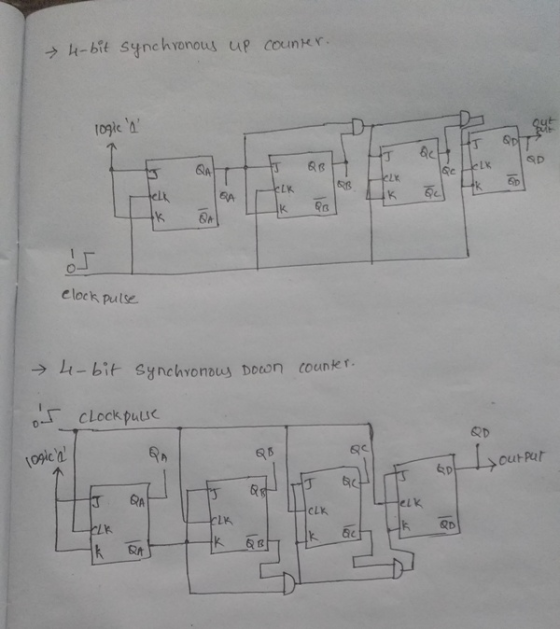
Need a schematic for a 4 bit synchronous up/down counter using two JK flip flops (74112)...
Need a schematic for a 4 bit synchronous up/down counter using two JK flip flops (74112) with the program Quartus II. I am using version 14.1. There should be a preset, clear, and clock input. Four outputs. Please complete the schematic and take a screenshot for me. Has to successfully pass compilation, thank you!
Homework Answers
Add Answer to:
Need a schematic for a 4 bit synchronous up/down counter using
two JK flip flops (74112)...
Using Proteus, design Synchronous 4 bit Up binary counter using JK flip flops (Use 74HC76 JK flipflop). The circuit count from 0000 to 1111, etc.
 Q2) 4-bit Synchronous Counter Using Proteus, design Synchronous 4 bit Up binary counter using JK flip flops (Use 74HC76 JK flipflop). The circuit count from 0000 to 1111, etc. Experiment procedure: طريقة اجراء التجربة a) Complete the circuit. You can use external gates based on the following conditions: o Flipflop A switches every clock. o Flipflop B switches when the output of flipflop A=1 o Flipflop C switches when the outputs of A-B=1 o Flipflop D switches when the outputs of A=B=C=1 b) What is the typical feature of...
Up-Down counter with enable using JK flip-flops: Design, construct and test a 2-bit counter that counts up or down.
Up-Down counter with enable using JK flip-flops: Design, construct and test a 2-bit counter that counts up or down. An enable input E determines whether the counter is on or off. If E = 0, the counter is disabled and remains in the present count even though clock pulses are applied to the flip-flops. If E= 1, the counter in enabled and a second input, x, determines the count direction. If x= 1, the circuit counts up with the sequence...
Part Ii Using positive logic, and an input variable x, design a MOD 4 Synchronous Counter to coun...
 Part Ii Using positive logic, and an input variable x, design a MOD 4 Synchronous Counter to count in a 2753,2753, etc. sequence vhen -0, and will count in a 3572.3572 etc. sequence vhen 1. Use 74112 Dual JK flip flops with Preset and Clear capabilities
Part Ii Using positive logic, and an input variable x, design a MOD 4 Synchronous Counter to count in a 2753,2753, etc. sequence vhen -0, and will count in a 3572.3572 etc. sequence vhen...
Part Ii Using positive logic, and an input variable x, design a MOD 4 Synchronous Counter to count in a 2753,2753, etc. sequence vhen -0, and will count in a 3572.3572 etc. sequence vhen 1. Use 74112 Dual JK flip flops with Preset and Clear capabilities
Part Ii Using positive logic, and an input variable x, design a MOD 4 Synchronous Counter to count in a 2753,2753, etc. sequence vhen -0, and will count in a 3572.3572 etc. sequence vhen...
Design a 4-bit binary up counter (like the following state diagram) using JK flip flops.
 Design a 4-bit binary up counter (like the following state diagram) using JK flip flops. State diagram. 0000 0001 11111 (a) Draw the state table with the input values for J K flip flops(b) Simplify the input equations by K map (c) Draw the logic diagram
Designa synchronous counter using jk flip flops with the following repeated sequence: 0,1,2,3
Designa synchronous counter using jk flip flops with the following repeated sequence: 0,1,2,3
Design serial (asynchronous) counter modulo 7 using synchronous flip-flops (T, D or JK). The counter should count up.
Design serial (asynchronous) counter modulo 7 using synchronous flip-flops (T, D or JK). The counter should count up.
Design a non-sequential synchronous counter using a positive edge triggered JK Flip Flops for the following...
 Design a non-sequential synchronous counter using a positive
edge triggered JK Flip Flops for the following output
0?2?3?5?4?7?6?0
Design a non-sequential synchronous counter using positive edge triggered JK Flip Flops for the following output 0 rightarrow 2 rightarrow 3 rightarrow 5 rightarrow 4 rightarrow 7 rightarrow 6 rightarrow 0
Design a non-sequential synchronous counter using a positive
edge triggered JK Flip Flops for the following output
0?2?3?5?4?7?6?0
Design a non-sequential synchronous counter using positive edge triggered JK Flip Flops for the following output 0 rightarrow 2 rightarrow 3 rightarrow 5 rightarrow 4 rightarrow 7 rightarrow 6 rightarrow 0
9) Using JK flip flops and in the space below, design a synchronous counter that counts...
 9) Using JK flip flops and in the space below, design a synchronous counter that counts up from 0 to 5 and recycles to 0. (Positive edge triggered, PRE & CLR active low) Show all connections except the power and ground inputs to the flip flops.
(a) Design an asynchronous Binary Coded Decimal (BCD) count-up counter using JK flip-flops. Draw the counter circuit clearly showing the configuration of the JK flip-flops and the necessary logic gat...
 (a) Design an asynchronous Binary Coded Decimal (BCD) count-up counter using JK flip-flops. Draw the counter circuit clearly showing the configuration of the JK flip-flops and the necessary logic gate(s). Sketch the input and output waveforms of this counter (7 Marks) (b) The binary up/down counter for a cargo lift controller in a 7-storey building has an up-down (UID) control input and a buzzer output (B). The buzzer will sound B 1) when the lift is at level 1 or...
We need to design a four-bit binary synchronous down counter using JK flip-flop. I'd appreciate it...
We need to design a four-bit binary synchronous down counter using JK flip-flop. I'd appreciate it if you could draw the truth and logic.
 Part Ii Using positive logic, and an input variable x, design a MOD 4 Synchronous Counter to count in a 2753,2753, etc. sequence vhen -0, and will count in a 3572.3572 etc. sequence vhen 1. Use 74112 Dual JK flip flops with Preset and Clear capabilities
Part Ii Using positive logic, and an input variable x, design a MOD 4 Synchronous Counter to count in a 2753,2753, etc. sequence vhen -0, and will count in a 3572.3572 etc. sequence vhen...
Part Ii Using positive logic, and an input variable x, design a MOD 4 Synchronous Counter to count in a 2753,2753, etc. sequence vhen -0, and will count in a 3572.3572 etc. sequence vhen 1. Use 74112 Dual JK flip flops with Preset and Clear capabilities
Part Ii Using positive logic, and an input variable x, design a MOD 4 Synchronous Counter to count in a 2753,2753, etc. sequence vhen -0, and will count in a 3572.3572 etc. sequence vhen...
 Design a non-sequential synchronous counter using a positive
edge triggered JK Flip Flops for the following output
0?2?3?5?4?7?6?0
Design a non-sequential synchronous counter using positive edge triggered JK Flip Flops for the following output 0 rightarrow 2 rightarrow 3 rightarrow 5 rightarrow 4 rightarrow 7 rightarrow 6 rightarrow 0
Design a non-sequential synchronous counter using a positive
edge triggered JK Flip Flops for the following output
0?2?3?5?4?7?6?0
Design a non-sequential synchronous counter using positive edge triggered JK Flip Flops for the following output 0 rightarrow 2 rightarrow 3 rightarrow 5 rightarrow 4 rightarrow 7 rightarrow 6 rightarrow 0
 9) Using JK flip flops and in the space below, design a synchronous counter that counts up from 0 to 5 and recycles to 0. (Positive edge triggered, PRE & CLR active low) Show all connections except the power and ground inputs to the flip flops.
 (a) Design an asynchronous Binary Coded Decimal (BCD) count-up counter using JK flip-flops. Draw the counter circuit clearly showing the configuration of the JK flip-flops and the necessary logic gate(s). Sketch the input and output waveforms of this counter (7 Marks) (b) The binary up/down counter for a cargo lift controller in a 7-storey building has an up-down (UID) control input and a buzzer output (B). The buzzer will sound B 1) when the lift is at level 1 or...
Most questions answered within 3 hours.
-
A business executive has the option to invest money in two
plans: Plan A guarantees that...
asked 1 hour ago -
Hello, can someone please help me answer this question?
How much heat is absorbed by a...
asked 1 hour ago -
. A marketing researcher conducted a survey of 25 shoppers
randomly selected at the local mall...
asked 1 hour ago -
Create an comprehensive response to the
following:
Antimicrobial agents work on a multitude of microbes (bacteria,...
asked 2 hours ago -
6.13 LAB: Step counter. Section 6.3.
A pedometer treats walking 2,000 steps as walking 1 mile....
asked 1 hour ago -
(14.2) A block of mass m = 10 kg riding on a frictionless
horizontal plane is...
asked 1 hour ago -
Use any search engine to search for articles about Starbucks
partnership with Tata Companies in India...
asked 1 hour ago -
Let’s say that for some reason Bank Excess Reserves suddenly
increase sharply. What effect would this...
asked 2 hours ago -
Given:
Curent Assets: $600,000
Total Assets: $2,600,000
Current Liabilities: $500,000
Total Liabilities: $1,700,000
What is the...
asked 2 hours ago -
1. What is a “Bankster”? What is insider trading? Why is it
illegal?
2. What is...
asked 2 hours ago -
A transverse wave on a cord is given by
D(x,t)=0.18sin(2.7x−61.0t), where Dand x are in m...
asked 2 hours ago -
ASSIGNMENT
ANSWER ANY TWO OF THE FOLLOWING IN 2-3 PARAGRAPHS OF EACH
QUESTION.
1: Where is...
asked 2 hours ago