
Homework Answers

Add Answer to:
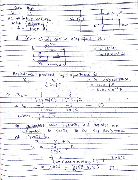
Assuming that Vin is a 1 Volt amplitude sinusoid at 1000FHz and zero phase, calculate Vout...
1) An input step voltage Vin(t)=10 u(t) Volt is applied to the circuit shown below. The...
 1) An input step voltage Vin(t)=10 u(t) Volt is applied to the circuit shown below. The initial voltage on the capacitor is zero. Using Laplace transform techniques, calculate the resulting output voltage Vout(t). R1 R2 Vout 2000 Vin c1 1000 1uF R3 1000
1) Assuming ideal op-amp characteristics, determine the gains (Vout/Vin) of the following amplifier circuits and the...
 1) Assuming ideal op-amp characteristics, determine the gains (Vout/Vin) of the following amplifier circuits and the indicated currents. You should assume that voltage saturation is not a factor. U2 Vin=2= 11 15 2 Oy v Vout out 12 | 1k 14 Vin=2v — 111K OU Vout | thi I4 W 1 10k 110 U5115 OPAMP IZR1114 R13 Vout 3k R15 1116 ISVR12 3k 114 R16 113 R14 11k c) Vin = 4V
esign three phase AC/DC converter with the following parameters - Vin (Line-Line) = 400 rms - Frequency = 50 Hz - Vout = 0 to 450V Simulate the converter under the following conditions 1- The load is...
esign three phase AC/DC converter with the following parameters - Vin (Line-Line) = 400 rms - Frequency = 50 Hz - Vout = 0 to 450V Simulate the converter under the following conditions 1- The load is Resistive, with 20Ω. Study the operation of the converter in term of: o Output voltage o Output current o Thyristor voltage and current o Relation of output voltage with firing angle alpha o Input and output harmonic spectrum.
Problem 5: Noisy Signal A signal generator generates a random sinusoid, X cos (2nt + Θ) whose amplitude is given by a random variable X uniformly distributed between-1 and 1, and phase Θ is an indepe...
 Problem 5: Noisy Signal A signal generator generates a random sinusoid, X cos (2nt + Θ) whose amplitude is given by a random variable X uniformly distributed between-1 and 1, and phase Θ is an independent random variable which takes each of the following values π 0, π with equal prob- ability. This signal's amplitude is additively corrupted by independent noise YN(0, 0.01) The output amplitude is denoted by Z, where Z-X +Y. Assuming that an estimator of X has...
Part 1: Gain =8, R1=5k, R2=20k, R5=100, and V1=1V. Find Vout/Vin. Part 2: Let R4=0 and...
 Part 1: Gain =8, R1=5k, R2=20k, R5=100, and V1=1V. Find
Vout/Vin.
Part 2: Let R4=0 and R3=∞. Find Vout/Vin. (Hint: make sure the
button called Enable Biased Voltage
Display is depressed) (Another Hint: when a resistance is zero,
short it; when a resistance is
infinity, delete it).
Part 3: Let R4=2k and R3=∞. Find Vout/Vin.
Part 4: Let R4=0 and R3=1000. Find Vout/Vin.
Part 5:Let R4=2k and R3=1000. Find Vout/Vin.
R1 Vout G1 5k R4 1k R5 100 V1 R2...
Part 1: Gain =8, R1=5k, R2=20k, R5=100, and V1=1V. Find
Vout/Vin.
Part 2: Let R4=0 and R3=∞. Find Vout/Vin. (Hint: make sure the
button called Enable Biased Voltage
Display is depressed) (Another Hint: when a resistance is zero,
short it; when a resistance is
infinity, delete it).
Part 3: Let R4=2k and R3=∞. Find Vout/Vin.
Part 4: Let R4=0 and R3=1000. Find Vout/Vin.
Part 5:Let R4=2k and R3=1000. Find Vout/Vin.
R1 Vout G1 5k R4 1k R5 100 V1 R2...
Question 1 For the flyback converter shown in Fig. 1, Vin is 30 V, Vout is 8 V, the output power is 30 w, 30 turns are...
 Question 1 For the flyback converter shown in Fig. 1, Vin is 30 V, Vout is 8 V, the output power is 30 w, 30 turns are fitted to winding Ww1, 15 turns are fitted to winding W2, the inductance of W1, L1, is 50 uH and the switching frequency is 200 kHz. The flyback converter operates in continuous conduction mode. Calculate the time for which S1 is switched on a. b. Calculate Aisı during the time S1 is switched...
I need help with numbers 4,6,7,8,9 please? 12 VDC 1.0 k ohms 10k ohms C3 1.0 uF C1 1.0 UF , R Load Baca 1 80 10k ohns 300 mVp-p 1.0 kHz 100 ohms .7k ohms C2 47uF 330 ohms 4. Calculate the following pa...
 I need help with numbers 4,6,7,8,9 please?
12 VDC 1.0 k ohms 10k ohms C3 1.0 uF C1 1.0 UF , R Load Baca 1 80 10k ohns 300 mVp-p 1.0 kHz 100 ohms .7k ohms C2 47uF 330 ohms 4. Calculate the following parameters assuming capacitor C2 has been removed from the circuit with the 1.0k2 resistor as the load. RIN BASE Av Vour 5. Construct the circuit shown on the previous page. Before connecting the AC supply, measure...
I need help with numbers 4,6,7,8,9 please?
12 VDC 1.0 k ohms 10k ohms C3 1.0 uF C1 1.0 UF , R Load Baca 1 80 10k ohns 300 mVp-p 1.0 kHz 100 ohms .7k ohms C2 47uF 330 ohms 4. Calculate the following parameters assuming capacitor C2 has been removed from the circuit with the 1.0k2 resistor as the load. RIN BASE Av Vour 5. Construct the circuit shown on the previous page. Before connecting the AC supply, measure...
(a) Design a inverting Schmitt trigger circuit to be used as a zero crossing detector with transition voltages about ±25...
 (a) Design a inverting Schmitt trigger circuit
to be used as a zero crossing detector with transition voltages
about ±25 mV. Assume the saturation voltages for the op–amp are ±13
V. Draw the voltage transfer characteristic (VTC), i.e., vout vs.
vin.
(b) Design an astable multivibrator to produce
a square signal with a frequency of 1 kHz using C=0.01 µF, R1 = 30
kΩ, and R2 = 20 kΩ. Sketch the circuit waveforms (vo, v +, and v −)
assuming...
(a) Design a inverting Schmitt trigger circuit
to be used as a zero crossing detector with transition voltages
about ±25 mV. Assume the saturation voltages for the op–amp are ±13
V. Draw the voltage transfer characteristic (VTC), i.e., vout vs.
vin.
(b) Design an astable multivibrator to produce
a square signal with a frequency of 1 kHz using C=0.01 µF, R1 = 30
kΩ, and R2 = 20 kΩ. Sketch the circuit waveforms (vo, v +, and v −)
assuming...
Vout should be a sinusoid signal of 12Vp-p Dc voltage to uA741 : +/-8.5V Please simulate...
 Vout should be a sinusoid signal of 12Vp-p
Dc voltage to uA741 : +/-8.5V
Please simulate as well
please help, im completely lost on this
this is all of the information
Experiment 5. RC Sinusoidal Oscillators PURPOSE: This laboratory provides an introduction to the background, analysis and design of sinusoidal oscillators using RC feedback networks and active devices to achieve the criteria for continuous oscillations to occur. EQUIPMENT REQUIRED : 1 Operational amplifier u.A741 1 CEU development station Resistors and...
Vout should be a sinusoid signal of 12Vp-p
Dc voltage to uA741 : +/-8.5V
Please simulate as well
please help, im completely lost on this
this is all of the information
Experiment 5. RC Sinusoidal Oscillators PURPOSE: This laboratory provides an introduction to the background, analysis and design of sinusoidal oscillators using RC feedback networks and active devices to achieve the criteria for continuous oscillations to occur. EQUIPMENT REQUIRED : 1 Operational amplifier u.A741 1 CEU development station Resistors and...
Question 3. Unregulated supply Rz IL Vin IR Ib (a) The circuit on the right shows...
 Question 3. Unregulated supply Rz IL Vin IR Ib (a) The circuit on the right shows a series regulator connected to the output of an unregulated power supply. The transistor has B =50, and a 6 volt Zener diode is used. When the load current, Il, is 1 amp the de input voltage from the unregulated supply, Vin, is 11 volt, VBE = 1 volt and the Zener diode current, Iz, is 20 mA. For these conditions, calculate Iz (i)...
 1) An input step voltage Vin(t)=10 u(t) Volt is applied to the circuit shown below. The initial voltage on the capacitor is zero. Using Laplace transform techniques, calculate the resulting output voltage Vout(t). R1 R2 Vout 2000 Vin c1 1000 1uF R3 1000
 1) Assuming ideal op-amp characteristics, determine the gains (Vout/Vin) of the following amplifier circuits and the indicated currents. You should assume that voltage saturation is not a factor. U2 Vin=2= 11 15 2 Oy v Vout out 12 | 1k 14 Vin=2v — 111K OU Vout | thi I4 W 1 10k 110 U5115 OPAMP IZR1114 R13 Vout 3k R15 1116 ISVR12 3k 114 R16 113 R14 11k c) Vin = 4V
 Problem 5: Noisy Signal A signal generator generates a random sinusoid, X cos (2nt + Θ) whose amplitude is given by a random variable X uniformly distributed between-1 and 1, and phase Θ is an independent random variable which takes each of the following values π 0, π with equal prob- ability. This signal's amplitude is additively corrupted by independent noise YN(0, 0.01) The output amplitude is denoted by Z, where Z-X +Y. Assuming that an estimator of X has...
 Part 1: Gain =8, R1=5k, R2=20k, R5=100, and V1=1V. Find
Vout/Vin.
Part 2: Let R4=0 and R3=∞. Find Vout/Vin. (Hint: make sure the
button called Enable Biased Voltage
Display is depressed) (Another Hint: when a resistance is zero,
short it; when a resistance is
infinity, delete it).
Part 3: Let R4=2k and R3=∞. Find Vout/Vin.
Part 4: Let R4=0 and R3=1000. Find Vout/Vin.
Part 5:Let R4=2k and R3=1000. Find Vout/Vin.
R1 Vout G1 5k R4 1k R5 100 V1 R2...
Part 1: Gain =8, R1=5k, R2=20k, R5=100, and V1=1V. Find
Vout/Vin.
Part 2: Let R4=0 and R3=∞. Find Vout/Vin. (Hint: make sure the
button called Enable Biased Voltage
Display is depressed) (Another Hint: when a resistance is zero,
short it; when a resistance is
infinity, delete it).
Part 3: Let R4=2k and R3=∞. Find Vout/Vin.
Part 4: Let R4=0 and R3=1000. Find Vout/Vin.
Part 5:Let R4=2k and R3=1000. Find Vout/Vin.
R1 Vout G1 5k R4 1k R5 100 V1 R2...
 Question 1 For the flyback converter shown in Fig. 1, Vin is 30 V, Vout is 8 V, the output power is 30 w, 30 turns are fitted to winding Ww1, 15 turns are fitted to winding W2, the inductance of W1, L1, is 50 uH and the switching frequency is 200 kHz. The flyback converter operates in continuous conduction mode. Calculate the time for which S1 is switched on a. b. Calculate Aisı during the time S1 is switched...
 I need help with numbers 4,6,7,8,9 please?
12 VDC 1.0 k ohms 10k ohms C3 1.0 uF C1 1.0 UF , R Load Baca 1 80 10k ohns 300 mVp-p 1.0 kHz 100 ohms .7k ohms C2 47uF 330 ohms 4. Calculate the following parameters assuming capacitor C2 has been removed from the circuit with the 1.0k2 resistor as the load. RIN BASE Av Vour 5. Construct the circuit shown on the previous page. Before connecting the AC supply, measure...
I need help with numbers 4,6,7,8,9 please?
12 VDC 1.0 k ohms 10k ohms C3 1.0 uF C1 1.0 UF , R Load Baca 1 80 10k ohns 300 mVp-p 1.0 kHz 100 ohms .7k ohms C2 47uF 330 ohms 4. Calculate the following parameters assuming capacitor C2 has been removed from the circuit with the 1.0k2 resistor as the load. RIN BASE Av Vour 5. Construct the circuit shown on the previous page. Before connecting the AC supply, measure...
 (a) Design a inverting Schmitt trigger circuit
to be used as a zero crossing detector with transition voltages
about ±25 mV. Assume the saturation voltages for the op–amp are ±13
V. Draw the voltage transfer characteristic (VTC), i.e., vout vs.
vin.
(b) Design an astable multivibrator to produce
a square signal with a frequency of 1 kHz using C=0.01 µF, R1 = 30
kΩ, and R2 = 20 kΩ. Sketch the circuit waveforms (vo, v +, and v −)
assuming...
(a) Design a inverting Schmitt trigger circuit
to be used as a zero crossing detector with transition voltages
about ±25 mV. Assume the saturation voltages for the op–amp are ±13
V. Draw the voltage transfer characteristic (VTC), i.e., vout vs.
vin.
(b) Design an astable multivibrator to produce
a square signal with a frequency of 1 kHz using C=0.01 µF, R1 = 30
kΩ, and R2 = 20 kΩ. Sketch the circuit waveforms (vo, v +, and v −)
assuming...
 Vout should be a sinusoid signal of 12Vp-p
Dc voltage to uA741 : +/-8.5V
Please simulate as well
please help, im completely lost on this
this is all of the information
Experiment 5. RC Sinusoidal Oscillators PURPOSE: This laboratory provides an introduction to the background, analysis and design of sinusoidal oscillators using RC feedback networks and active devices to achieve the criteria for continuous oscillations to occur. EQUIPMENT REQUIRED : 1 Operational amplifier u.A741 1 CEU development station Resistors and...
Vout should be a sinusoid signal of 12Vp-p
Dc voltage to uA741 : +/-8.5V
Please simulate as well
please help, im completely lost on this
this is all of the information
Experiment 5. RC Sinusoidal Oscillators PURPOSE: This laboratory provides an introduction to the background, analysis and design of sinusoidal oscillators using RC feedback networks and active devices to achieve the criteria for continuous oscillations to occur. EQUIPMENT REQUIRED : 1 Operational amplifier u.A741 1 CEU development station Resistors and...
 Question 3. Unregulated supply Rz IL Vin IR Ib (a) The circuit on the right shows a series regulator connected to the output of an unregulated power supply. The transistor has B =50, and a 6 volt Zener diode is used. When the load current, Il, is 1 amp the de input voltage from the unregulated supply, Vin, is 11 volt, VBE = 1 volt and the Zener diode current, Iz, is 20 mA. For these conditions, calculate Iz (i)...
Most questions answered within 3 hours.
-
A perfect gas undergoes an isentropic process such that its
volume doubles. If the ratio of...
asked 7 minutes ago -
list the elements in groups 3A to 6A in the same order as in the
periodic...
asked 17 minutes ago -
Estimating effect size. Peng and Chen (2014)
evaluated effect size estimates for various tests. In their...
asked 26 minutes ago -
Write a script in MySQL that creates and calls a stored
procedure name test. This procedure...
asked 27 minutes ago -
If we test the following: H0: μ = 17
vs. H1: μ ≠ 17 and the...
asked 37 minutes ago -
in the past year TVG had revenues of 3 million, cost
of goods sold of $25...
asked 43 minutes ago -
4) In a polypeptide, which bond cannot rotate because of its
partial double bond character?
The...
asked 1 hour ago -
Assume that in the short run L = 1,000 and K = 100. 1. What is...
asked 1 hour ago -
At a given temperature, 2.06 atm of H2 and 3.7 atm of Br2 are
mixed and...
asked 1 hour ago -
Sodium reacts with Hydrochloric acid to form sodium chloride and
hydrogen gas. 2Na(s)+ 2 HCl(aq)-> 2...
asked 1 hour ago -
The following circuits (1 & 2) are combined to form a
series-parallel circuit and resulting circuit...
asked 1 hour ago -
Feynman's use of path integrals can make some of the transition
from quantum scale to real...
asked 1 hour ago