

Homework Answers

Add Answer to:
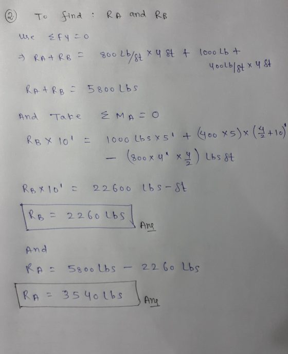
Calculate the magnitude of FB and Fc for the beam, loaded as shown in the figure...
4 The beam in the figure below is in equilibrium and loaded as shown.c calculations HOW...
 4 The beam in the figure below is in equilibrium and loaded as shown.c calculations HOW is in equilibrium and loaded as shown Calculate the magnitude of FA and FD. Show all 15 ft 10 ft 10 ft Fe=50,000 lbs Fo=20,000 lbs w=4,000 lbs/ft B 30°
Problem 3 A simple beam AB is loaded as shown in the figure. (a) Calculate the...
 Problem 3 A simple beam AB is loaded as shown in the figure. (a) Calculate the required section modulus Sif Gallow - 18,000 psi, L-32 ft. P-2900 lb, and q- 450 lb/ft. Then select a suitable I-beam (S shape) from Table F-2(a). Appendix F. and recalculate S taking into account the weight of the beam. Select a new beam size if necessary (b) What is the maximum load P that can be applied to your final beam selec tion in...
2. For the beam loaded as shown in the figure, find the following The beam is...
 2. For the beam loaded as shown in the figure, find the following The beam is made of steel, has a rectangular cross section with a width of 2 in. and a height of 2 in. a. b. c. The reactions on the beam. The shear and moment diagrams. The deflection of the beam at the end of the overhang 20 in 15 in 10 in 500 lb 100 lb/in
The figure below shows three forces of magnitude FA=22.1 N, FB=23.1 N, and FC=27.3 N acting...
 The figure below shows three forces of magnitude FA=22.1 N,
FB=23.1 N, and FC=27.3 N acting on an object which is free to
rotate about a fixed axis at the point O as shown in the figure.
The respective distances from point O are RA=4.6 m, RB=3.5 m, and
RC=1.0 m. If the tangential acceleration of point A is aT=2.1, what
is the rotational inertia of the object?
The figure below shows three forces of magnitude Fa=22.1 N, FB=23.1 N,...
The figure below shows three forces of magnitude FA=22.1 N,
FB=23.1 N, and FC=27.3 N acting on an object which is free to
rotate about a fixed axis at the point O as shown in the figure.
The respective distances from point O are RA=4.6 m, RB=3.5 m, and
RC=1.0 m. If the tangential acceleration of point A is aT=2.1, what
is the rotational inertia of the object?
The figure below shows three forces of magnitude Fa=22.1 N, FB=23.1 N,...
Determine the reactions at the supports of the beam which is loaded as shown. Assume w1...
 Determine the reactions at the supports of the beam which is
loaded as shown.
Assume w1 = 600 N/m, w2 =
220 N/m, a = 7.1 m, b = 1.8 m.
Determine the reactions at the supports of the beam which is loaded as shown. Assume w1 = 600 N/m, W2 = 220 N/m, a = 7.1m, b = 1.8 m. w w OB b b d Answers Ax - N Ay = N By = N
Determine the reactions at the supports of the beam which is
loaded as shown.
Assume w1 = 600 N/m, w2 =
220 N/m, a = 7.1 m, b = 1.8 m.
Determine the reactions at the supports of the beam which is loaded as shown. Assume w1 = 600 N/m, W2 = 220 N/m, a = 7.1m, b = 1.8 m. w w OB b b d Answers Ax - N Ay = N By = N
4. A cantilever beam is loaded as shown in the figure. Using the method of sections...
 4. A cantilever beam is loaded as shown in the figure. Using the method of sections or the integration method, draw the shear force diagram and the bending moment diagram. If the beam cross-section is a 9 inch square, find the maximum bending stress 1200 lb 800 lb/ft 9" B 9" A Beam cross-section 8 ft 8 ft
1. For the beam loaded as shown in the figure, find the following: The beam is...
 1. For the beam loaded as shown in the figure, find the following: The beam is rectangular and made of steel, it has a width of 20mm and a height of 40mm. Find: a. The reactions on the beam. b. The maximum bending stress at the base. c. The maximum deflection. F=850N 0.2 m 1 W=80N/m 0.7 m
1. For the beam loaded as shown in the figure, find the following: The beam is...
 1. For the beam loaded as shown in the figure, find the following: The beam is rectangular and made of steel, it has a width of 20mm and a height of 40mm. Find: a. b. c. The reactions on the beam. The maximum principle stress at the base. The maximum slope and the maximum deflection. F-850N 0.2 m w-80N/m 0.7 m
The figure below shows three forces of magnitude FA=22.1 N, FB=23.1 N, and FC=27.3 N acting...
 The figure below shows three forces of magnitude
FA=22.1 N, FB=23.1 N, and FC=27.3
N acting on an object which is free to rotate about a fixed axis at
the point O as shown in the figure. The respective distances from
point O are RA=4.6 m, RB=3.5 m, and
RC=1.0 m. If the tangential acceleration of point A is
aT=2.1, what is the rotational inertia of the
object?
F Fc С 135°C A 160° 90° FB B
The figure below shows three forces of magnitude
FA=22.1 N, FB=23.1 N, and FC=27.3
N acting on an object which is free to rotate about a fixed axis at
the point O as shown in the figure. The respective distances from
point O are RA=4.6 m, RB=3.5 m, and
RC=1.0 m. If the tangential acceleration of point A is
aT=2.1, what is the rotational inertia of the
object?
F Fc С 135°C A 160° 90° FB B
The simply support beam below is loaded as shown. O = 45° 75 kip 30 kip/ft...
 The simply support beam below is loaded as shown. O = 45° 75 kip 30 kip/ft 500 kip-ft me 1 ft 3 ft 1.5 ft 2.5 ft 2.5ft The exact value of the normal force (N), shear force (V), and bending moment (M) at a distance of x=7 feet. Be sure to indicate both magnitude and direction with arrows. (a) FBD and support reactions (b) FBD to find internal forces (c) Calculate N, V, and M at 7 feet
 4 The beam in the figure below is in equilibrium and loaded as shown.c calculations HOW is in equilibrium and loaded as shown Calculate the magnitude of FA and FD. Show all 15 ft 10 ft 10 ft Fe=50,000 lbs Fo=20,000 lbs w=4,000 lbs/ft B 30°
 Problem 3 A simple beam AB is loaded as shown in the figure. (a) Calculate the required section modulus Sif Gallow - 18,000 psi, L-32 ft. P-2900 lb, and q- 450 lb/ft. Then select a suitable I-beam (S shape) from Table F-2(a). Appendix F. and recalculate S taking into account the weight of the beam. Select a new beam size if necessary (b) What is the maximum load P that can be applied to your final beam selec tion in...
 2. For the beam loaded as shown in the figure, find the following The beam is made of steel, has a rectangular cross section with a width of 2 in. and a height of 2 in. a. b. c. The reactions on the beam. The shear and moment diagrams. The deflection of the beam at the end of the overhang 20 in 15 in 10 in 500 lb 100 lb/in
 The figure below shows three forces of magnitude FA=22.1 N,
FB=23.1 N, and FC=27.3 N acting on an object which is free to
rotate about a fixed axis at the point O as shown in the figure.
The respective distances from point O are RA=4.6 m, RB=3.5 m, and
RC=1.0 m. If the tangential acceleration of point A is aT=2.1, what
is the rotational inertia of the object?
The figure below shows three forces of magnitude Fa=22.1 N, FB=23.1 N,...
The figure below shows three forces of magnitude FA=22.1 N,
FB=23.1 N, and FC=27.3 N acting on an object which is free to
rotate about a fixed axis at the point O as shown in the figure.
The respective distances from point O are RA=4.6 m, RB=3.5 m, and
RC=1.0 m. If the tangential acceleration of point A is aT=2.1, what
is the rotational inertia of the object?
The figure below shows three forces of magnitude Fa=22.1 N, FB=23.1 N,...
 Determine the reactions at the supports of the beam which is
loaded as shown.
Assume w1 = 600 N/m, w2 =
220 N/m, a = 7.1 m, b = 1.8 m.
Determine the reactions at the supports of the beam which is loaded as shown. Assume w1 = 600 N/m, W2 = 220 N/m, a = 7.1m, b = 1.8 m. w w OB b b d Answers Ax - N Ay = N By = N
Determine the reactions at the supports of the beam which is
loaded as shown.
Assume w1 = 600 N/m, w2 =
220 N/m, a = 7.1 m, b = 1.8 m.
Determine the reactions at the supports of the beam which is loaded as shown. Assume w1 = 600 N/m, W2 = 220 N/m, a = 7.1m, b = 1.8 m. w w OB b b d Answers Ax - N Ay = N By = N
 4. A cantilever beam is loaded as shown in the figure. Using the method of sections or the integration method, draw the shear force diagram and the bending moment diagram. If the beam cross-section is a 9 inch square, find the maximum bending stress 1200 lb 800 lb/ft 9" B 9" A Beam cross-section 8 ft 8 ft
 1. For the beam loaded as shown in the figure, find the following: The beam is rectangular and made of steel, it has a width of 20mm and a height of 40mm. Find: a. The reactions on the beam. b. The maximum bending stress at the base. c. The maximum deflection. F=850N 0.2 m 1 W=80N/m 0.7 m
 1. For the beam loaded as shown in the figure, find the following: The beam is rectangular and made of steel, it has a width of 20mm and a height of 40mm. Find: a. b. c. The reactions on the beam. The maximum principle stress at the base. The maximum slope and the maximum deflection. F-850N 0.2 m w-80N/m 0.7 m
 The figure below shows three forces of magnitude
FA=22.1 N, FB=23.1 N, and FC=27.3
N acting on an object which is free to rotate about a fixed axis at
the point O as shown in the figure. The respective distances from
point O are RA=4.6 m, RB=3.5 m, and
RC=1.0 m. If the tangential acceleration of point A is
aT=2.1, what is the rotational inertia of the
object?
F Fc С 135°C A 160° 90° FB B
The figure below shows three forces of magnitude
FA=22.1 N, FB=23.1 N, and FC=27.3
N acting on an object which is free to rotate about a fixed axis at
the point O as shown in the figure. The respective distances from
point O are RA=4.6 m, RB=3.5 m, and
RC=1.0 m. If the tangential acceleration of point A is
aT=2.1, what is the rotational inertia of the
object?
F Fc С 135°C A 160° 90° FB B
 The simply support beam below is loaded as shown. O = 45° 75 kip 30 kip/ft 500 kip-ft me 1 ft 3 ft 1.5 ft 2.5 ft 2.5ft The exact value of the normal force (N), shear force (V), and bending moment (M) at a distance of x=7 feet. Be sure to indicate both magnitude and direction with arrows. (a) FBD and support reactions (b) FBD to find internal forces (c) Calculate N, V, and M at 7 feet
Most questions answered within 3 hours.
-
Write the equilibrium expression for the dissociation in
water for CH5N, C2H5O2COOH, H3AsO4, KClO2, HC2H2ClO2.
asked 12 seconds from now -
Wildhorse Company follows the practice of pricing its inventory
at the lower-of-cost-or-market, on an individual-item
basis....
asked 35 minutes ago -
3. (10 pts) You grow a corn crop that yields 150 bushels ac-1,
with the following...
asked 24 minutes ago -
7. The term Six Sigma refers to:
Select one:
a. The control limits established in a...
asked 34 minutes ago -
For the following reaction: A(g) + 2 B(g) ⇌ 2 C(g) Calculate the
equilibrium constant K...
asked 36 minutes ago -
Which of the following best describes tidal volume? options:
1.The amount of oxygen in the air...
asked 52 minutes ago -
1. Smaller cost distortions occur when the traditional systems'
single indirect-cost rate and the activity-cost-driver rates:...
asked 1 hour ago -
Using either a FMECA approach or some other appropriate RCA
tool, identify five risk treatment actions...
asked 1 hour ago -
If for a test the P-value is between 0.0025 and 0.005, what
conclusion can you draw?...
asked 1 hour ago -
Using Python. Write a function clean2(aList) that takes a list
of integers aList as argument, and...
asked 1 hour ago -
Intrapreneurship is defined as the
development of an enterprise culture with an existing (Nandan,
2009). An...
asked 1 hour ago -
QUESTION 1 Tamiflu is a drug used to treat influenza. A study
found that Tamiflu reduced...
asked 1 hour ago