Please clear your handwriting and explain your answers

Homework Answers


Add Answer to:
Please clear your handwriting and explain your
answers
A voltage doubling circuit is to be designed...
For your choice of input voltage, load resistor and the value of the ripple voltage (as percent of Vdc) design a circuit for the half-wave rectifier. Assuming the value of Van for the diode, calc...
 For your choice of input voltage, load resistor and the value of the ripple voltage (as percent of Vdc) design a circuit for the half-wave rectifier. Assuming the value of Van for the diode, calculate theoretically all parameters of the rectifier: Vp, Vdc, Idc, C, Isc, PIV and diode conducting interval. Simulate the designed circuit first without the capacitor filter and show on the graphs of the input, output and diode voltages and load and diode currents. Show on the...
QUESTION (2) The diodes are ideal except with an on-voltage of 0.7V. The input voltage source...
 QUESTION (2) The diodes are ideal except with an on-voltage of 0.7V. The input voltage source vIN is a 100Hz, 50% duty cycle square-wave with voltage levels of OV and +10V. The load resistance, R = 1002 DL D a) If the ripple voltage, V 0.5V, sketch the output waveform for several input cycles. What is the average DC output voltage vo + D. C R (6 points) Vo VIN b) What would be the minimum value of C (in...
please clear your handwriting and explain your answer 4) Problem 2-9: Page 71 [2 points An...
 please clear your handwriting and explain your answer
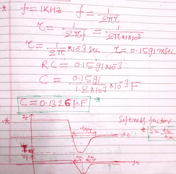
4) Problem 2-9: Page 71 [2 points An amplifier has an input coupling capacitor of 30 HF and an input resistance of 20 k2 Determine the lowest square wave frequency that can be applied as an input if the output tilt is not to exceed 5%
4) Problem 2-9: Page 71 [2 points An amplifier has an input coupling capacitor of 30 HF and an input resistance of 20 k2 Determine the...
please clear your handwriting and explain your answer
4) Problem 2-9: Page 71 [2 points An amplifier has an input coupling capacitor of 30 HF and an input resistance of 20 k2 Determine the lowest square wave frequency that can be applied as an input if the output tilt is not to exceed 5%
4) Problem 2-9: Page 71 [2 points An amplifier has an input coupling capacitor of 30 HF and an input resistance of 20 k2 Determine the...
Could younplease help me go through the solution of this question. b c d expecting a detailed exp...
 could younplease help me go through the solution of this question.
b c d
expecting a detailed explanation.
Thanks
5. A circuit co nsists of a diode, resistor and capacitor as shown in Figure 11 and is driven by a 50 Hz sinusoidal waveform. Assume that the diode has a forward threshold voltage of 0.7 V an "on resistance" of 0.1 2 and a reverse breakdown of 20 V Sketch the I - V behaviour of the diode. (a) 13...
could younplease help me go through the solution of this question.
b c d
expecting a detailed explanation.
Thanks
5. A circuit co nsists of a diode, resistor and capacitor as shown in Figure 11 and is driven by a 50 Hz sinusoidal waveform. Assume that the diode has a forward threshold voltage of 0.7 V an "on resistance" of 0.1 2 and a reverse breakdown of 20 V Sketch the I - V behaviour of the diode. (a) 13...
Please note that D4 is the one that was destroyed not D1. Please I posted this but they answer it...
 Please note that D4 is the one that was destroyed not D1.
Please I posted this but they answer it differently
QUESTION (2) Due to an abnormal operating condition, Diode D4 in this full-wave rectifier circuit was suddenly destroyed, and stopped Vconducting in both forward and reverse directions (i.e. open circuit) C- R Assume that all other diodes are ideal with zero forward voltage drop and that the time constant RC- 5 ms. stt) 10V For a 1 kHz triangular...
Please note that D4 is the one that was destroyed not D1.
Please I posted this but they answer it differently
QUESTION (2) Due to an abnormal operating condition, Diode D4 in this full-wave rectifier circuit was suddenly destroyed, and stopped Vconducting in both forward and reverse directions (i.e. open circuit) C- R Assume that all other diodes are ideal with zero forward voltage drop and that the time constant RC- 5 ms. stt) 10V For a 1 kHz triangular...
A Buck-boost converter has an output voltage 100 V, output power 60 W and input voltage...
A Buck-boost converter has an output voltage 100 V, output power 60 W and input voltage 12 V. Switching frequency is 15 kHz. Calculate duty ratios for the switch and the diode. Find values for the inductor L and capacitor C, when the allowed output voltage ripple is ±0.15 % and the inductor current ripple is ±1 % (of the average value). If the on-time of the switch has an inaccuracy of ±50 ns, what is the new output voltage...
It is required to use a FULL-wave rectifier to design a dc power supply that provides...
It is required to use a FULL-wave rectifier to design a dc power supply that provides an average dc output voltage of 15 V. A maximum ripple voltage of ±1 V is allowed on the output voltage. The output voltage will feed a load resistance of 250 Ω. Assume a sinusoidal input voltage with the frequency of 60 Hz. Do not include a Zener diode in your design. (Assume V_D0)* = 0.7 V). a) Draw the circuit diagram. b) Calculate...
please help Question 1 Consider the following circuit, where the reverse saturation current (Is) is the...
 please help
Question 1 Consider the following circuit, where the reverse saturation current (Is) is the same for each diode. D2 o Vo Di Vi WWW R 32 23 a. b. Determine an algebraic expression for V1, for a given Vo, and Is. Given an Is of 40 FA and R1 = 3.3 kl , determine the Vi that produces an output voltage (V.) of 0.625 V. C. Recalculate question-b if Is were to be a thousand times greater at...
please help
Question 1 Consider the following circuit, where the reverse saturation current (Is) is the same for each diode. D2 o Vo Di Vi WWW R 32 23 a. b. Determine an algebraic expression for V1, for a given Vo, and Is. Given an Is of 40 FA and R1 = 3.3 kl , determine the Vi that produces an output voltage (V.) of 0.625 V. C. Recalculate question-b if Is were to be a thousand times greater at...
QUESTION 5 (15 points) a. You have a power supply which is a full-wave rectifier with a capacitor filter. It operates f...
 QUESTION 5 (15 points) a. You have a power supply which is a full-wave rectifier with a capacitor filter. It operates from the mains and provides an output of Voc-20 V with 20% ripple, when the load current is 2 A Calculate the maximum and minimum values of the output waveform of this power supply. b. Now you will design a series voltage regulator between the power supply described in part (a) and an electronic device operating at 12 VDC...
To design a high efficiency d.c., to d.c power converter with the given specifications min 10V max 15V nominal (regulated) 8V Input voltage: Output voltage: Nominal load current: 4A Inductor current...
 To design a high efficiency d.c., to d.c power converter with the given specifications min 10V max 15V nominal (regulated) 8V Input voltage: Output voltage: Nominal load current: 4A Inductor current ripple: 0.1A max Switching frequency: 30 kHz Output voltage ripple: 20 mV Define a suitable power circuit topology to meet the above specification? Sketch a circuit diagram of the chosen power circuit topology (a) Define the minimum and maximum duty cycles assuming that the control circuit keeps the output...
 For your choice of input voltage, load resistor and the value of the ripple voltage (as percent of Vdc) design a circuit for the half-wave rectifier. Assuming the value of Van for the diode, calculate theoretically all parameters of the rectifier: Vp, Vdc, Idc, C, Isc, PIV and diode conducting interval. Simulate the designed circuit first without the capacitor filter and show on the graphs of the input, output and diode voltages and load and diode currents. Show on the...
 QUESTION (2) The diodes are ideal except with an on-voltage of 0.7V. The input voltage source vIN is a 100Hz, 50% duty cycle square-wave with voltage levels of OV and +10V. The load resistance, R = 1002 DL D a) If the ripple voltage, V 0.5V, sketch the output waveform for several input cycles. What is the average DC output voltage vo + D. C R (6 points) Vo VIN b) What would be the minimum value of C (in...
 please clear your handwriting and explain your answer
4) Problem 2-9: Page 71 [2 points An amplifier has an input coupling capacitor of 30 HF and an input resistance of 20 k2 Determine the lowest square wave frequency that can be applied as an input if the output tilt is not to exceed 5%
4) Problem 2-9: Page 71 [2 points An amplifier has an input coupling capacitor of 30 HF and an input resistance of 20 k2 Determine the...
please clear your handwriting and explain your answer
4) Problem 2-9: Page 71 [2 points An amplifier has an input coupling capacitor of 30 HF and an input resistance of 20 k2 Determine the lowest square wave frequency that can be applied as an input if the output tilt is not to exceed 5%
4) Problem 2-9: Page 71 [2 points An amplifier has an input coupling capacitor of 30 HF and an input resistance of 20 k2 Determine the...
 could younplease help me go through the solution of this question.
b c d
expecting a detailed explanation.
Thanks
5. A circuit co nsists of a diode, resistor and capacitor as shown in Figure 11 and is driven by a 50 Hz sinusoidal waveform. Assume that the diode has a forward threshold voltage of 0.7 V an "on resistance" of 0.1 2 and a reverse breakdown of 20 V Sketch the I - V behaviour of the diode. (a) 13...
could younplease help me go through the solution of this question.
b c d
expecting a detailed explanation.
Thanks
5. A circuit co nsists of a diode, resistor and capacitor as shown in Figure 11 and is driven by a 50 Hz sinusoidal waveform. Assume that the diode has a forward threshold voltage of 0.7 V an "on resistance" of 0.1 2 and a reverse breakdown of 20 V Sketch the I - V behaviour of the diode. (a) 13...
 Please note that D4 is the one that was destroyed not D1.
Please I posted this but they answer it differently
QUESTION (2) Due to an abnormal operating condition, Diode D4 in this full-wave rectifier circuit was suddenly destroyed, and stopped Vconducting in both forward and reverse directions (i.e. open circuit) C- R Assume that all other diodes are ideal with zero forward voltage drop and that the time constant RC- 5 ms. stt) 10V For a 1 kHz triangular...
Please note that D4 is the one that was destroyed not D1.
Please I posted this but they answer it differently
QUESTION (2) Due to an abnormal operating condition, Diode D4 in this full-wave rectifier circuit was suddenly destroyed, and stopped Vconducting in both forward and reverse directions (i.e. open circuit) C- R Assume that all other diodes are ideal with zero forward voltage drop and that the time constant RC- 5 ms. stt) 10V For a 1 kHz triangular...
 please help
Question 1 Consider the following circuit, where the reverse saturation current (Is) is the same for each diode. D2 o Vo Di Vi WWW R 32 23 a. b. Determine an algebraic expression for V1, for a given Vo, and Is. Given an Is of 40 FA and R1 = 3.3 kl , determine the Vi that produces an output voltage (V.) of 0.625 V. C. Recalculate question-b if Is were to be a thousand times greater at...
please help
Question 1 Consider the following circuit, where the reverse saturation current (Is) is the same for each diode. D2 o Vo Di Vi WWW R 32 23 a. b. Determine an algebraic expression for V1, for a given Vo, and Is. Given an Is of 40 FA and R1 = 3.3 kl , determine the Vi that produces an output voltage (V.) of 0.625 V. C. Recalculate question-b if Is were to be a thousand times greater at...
 QUESTION 5 (15 points) a. You have a power supply which is a full-wave rectifier with a capacitor filter. It operates from the mains and provides an output of Voc-20 V with 20% ripple, when the load current is 2 A Calculate the maximum and minimum values of the output waveform of this power supply. b. Now you will design a series voltage regulator between the power supply described in part (a) and an electronic device operating at 12 VDC...
 To design a high efficiency d.c., to d.c power converter with the given specifications min 10V max 15V nominal (regulated) 8V Input voltage: Output voltage: Nominal load current: 4A Inductor current ripple: 0.1A max Switching frequency: 30 kHz Output voltage ripple: 20 mV Define a suitable power circuit topology to meet the above specification? Sketch a circuit diagram of the chosen power circuit topology (a) Define the minimum and maximum duty cycles assuming that the control circuit keeps the output...
Most questions answered within 3 hours.
-
A statistics student finds herself struggling with a newspaper
article stating that only eighteen percent of...
asked 18 minutes ago -
People with beriberi, a disease caused by a thiamin deficiency,
have elevated levels of blood pyruvate...
asked 4 minutes ago -
PYTHON Programming Exercise 2: Create a Simple Cost Calculator
Write a program that displays input fields...
asked 10 minutes ago -
1.Seki agreed that Groupon could sell 18 hot air
balloon rides on his Magical Adventures company...
asked 11 minutes ago -
A cohort study is conducted to determine whether smoking is
associated with an increased risk of...
asked 17 minutes ago -
Create the pseudo-code/flowchart for an application class named
Monogram. Its main() method inputs three variables that...
asked 18 minutes ago -
How many liters of water are required to dissolve 1.00 g of
silver chromate? Express your...
asked 20 minutes ago -
Hot: T_inlet = 80, T_out = 65
Cold: T_inlet = 10, T_out = 25
Explain in...
asked 21 minutes ago -
Two protons fly in different directions and collide. They both
have a total energy of 1.5...
asked 30 minutes ago -
What is the oxidation number of each atom in sodium phosphate,
Na3PO4?
>>> SHOW YOUR WORK...
asked 36 minutes ago -
D company purchased goods with a list price of $60000, subject
to trade discounts of 20%...
asked 39 minutes ago -
Transposable elements make up more than 40% of the human genome
and are inserted more-or-less randomly...
asked 50 minutes ago