

0-7 43 10 C
Homework Answers

Add Answer to:
Could younplease help me go through the solution of this question. b c d expecting a detailed exp...
QUESTION 5 (15 points) a. You have a power supply which is a full-wave rectifier with a capacitor filter. It operates f...
 QUESTION 5 (15 points) a. You have a power supply which is a full-wave rectifier with a capacitor filter. It operates from the mains and provides an output of Voc-20 V with 20% ripple, when the load current is 2 A Calculate the maximum and minimum values of the output waveform of this power supply. b. Now you will design a series voltage regulator between the power supply described in part (a) and an electronic device operating at 12 VDC...
QUESTION (2) The diodes are ideal except with an on-voltage of 0.7V. The input voltage source...
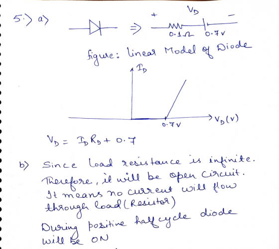
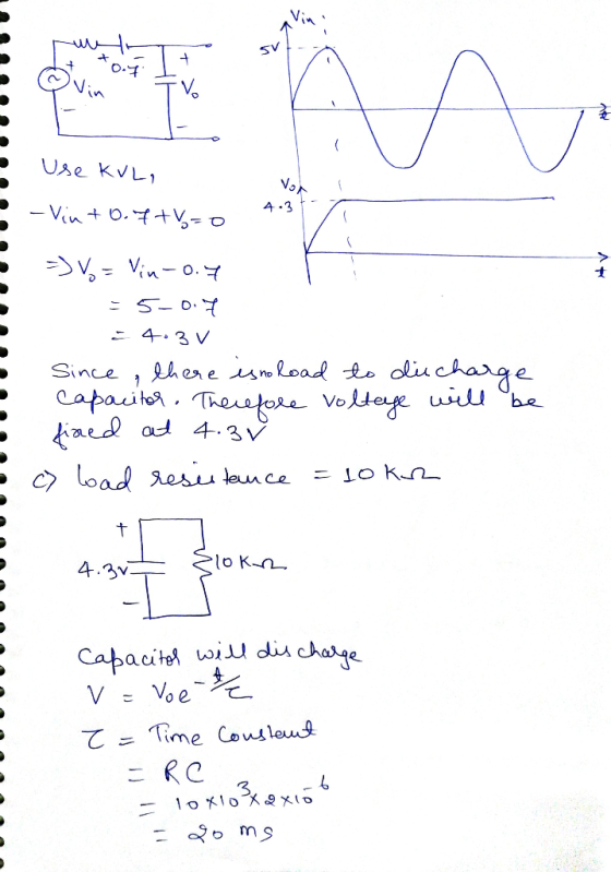
 QUESTION (2) The diodes are ideal except with an on-voltage of 0.7V. The input voltage source vIN is a 100Hz, 50% duty cycle square-wave with voltage levels of OV and +10V. The load resistance, R = 1002 DL D a) If the ripple voltage, V 0.5V, sketch the output waveform for several input cycles. What is the average DC output voltage vo + D. C R (6 points) Vo VIN b) What would be the minimum value of C (in...
done on pspice thank you Part IV: Diode Rectifiers Procedure: 1. Build the circuit model for...
 done on pspice thank you
Part IV: Diode Rectifiers Procedure: 1. Build the circuit model for full-wave diode rectifier in PSpice as shown in Fig. 4. The value of the load resistor is 10 k22. The input AC voltage source (VSIN in PSpice) is configured at 100 Hz and 20 V (peak-to- peak) in sinusoidal waveform. O 10K V.(t) V(A) A Figure 4. Circuit configuration for full-wave diode rectifier 2. Run the simulation and save the input and output voltage...
done on pspice thank you
Part IV: Diode Rectifiers Procedure: 1. Build the circuit model for full-wave diode rectifier in PSpice as shown in Fig. 4. The value of the load resistor is 10 k22. The input AC voltage source (VSIN in PSpice) is configured at 100 Hz and 20 V (peak-to- peak) in sinusoidal waveform. O 10K V.(t) V(A) A Figure 4. Circuit configuration for full-wave diode rectifier 2. Run the simulation and save the input and output voltage...
Design a FULL WAVE BRIDGE RECTIFIER circuit that will: Take 120volts ac, 60 hz, sinusoidal waveform...
 Design a FULL WAVE BRIDGE RECTIFIER circuit that will:
Take 120volts ac, 60 hz, sinusoidal waveform and convert
it to a “regulated “dc value
giving 12 volts +, - 1 volt across a 2000-ohm output
load resistor with no more than 2%
ripple voltage.
You may assume:
a. An ideal power transformer as discussed in class.
b. For hand computations, you must assume a diode given by
Figure 4.8 page 185.
c. A filter capacitor sized per the textbook equation...
Design a FULL WAVE BRIDGE RECTIFIER circuit that will:
Take 120volts ac, 60 hz, sinusoidal waveform and convert
it to a “regulated “dc value
giving 12 volts +, - 1 volt across a 2000-ohm output
load resistor with no more than 2%
ripple voltage.
You may assume:
a. An ideal power transformer as discussed in class.
b. For hand computations, you must assume a diode given by
Figure 4.8 page 185.
c. A filter capacitor sized per the textbook equation...
Problems,,,,,
 1 2
+
–
i(t)
C R
L
iT i(t)
iD
+
–
L C R
1. Analysis and design of a buck-boost converter: A buck-boost converter is illustrated in Fig. 1(a),
and a practical implementation using a transistor and diode is shown in Fig. 1(b).
+
(a)
Vg
v
Figure 1 Buck–boost converter
of Problem 1: (a) ideal converter
circuit, (b) implementation using
MOSFET and diode.
–
Q1
D1
(b) +
Vg
v
Page 2
iL
(t) + vL...
1 2
+
–
i(t)
C R
L
iT i(t)
iD
+
–
L C R
1. Analysis and design of a buck-boost converter: A buck-boost converter is illustrated in Fig. 1(a),
and a practical implementation using a transistor and diode is shown in Fig. 1(b).
+
(a)
Vg
v
Figure 1 Buck–boost converter
of Problem 1: (a) ideal converter
circuit, (b) implementation using
MOSFET and diode.
–
Q1
D1
(b) +
Vg
v
Page 2
iL
(t) + vL...
A common source amplifier circuit based on a single n-channel MOSFET is shown in Figure 4b. Assume that the transconductance gm-60 mS (equivalent to mA/ V) and drain source resistance, os,...
 A common source amplifier circuit based on a single n-channel MOSFET is shown in Figure 4b. Assume that the transconductance gm-60 mS (equivalent to mA/ V) and drain source resistance, os, is so large it may be neglected. 0) Calculate the open circuit voltage gain Av Yout/ Vis. i) The amplifier has a load of 10 k2. Determine the current gain Va. = 12 V 150k 4k3 Vout Vin 200k GND = 0 V Figure 4b a) State the name...
Be detailed in solving the question please 6. Rectifier] Given the rectifier circuit with filter capacitor...
 Be detailed in solving the question please
6. Rectifier] Given the rectifier circuit with filter capacitor where Vs = 15 cos(2760) V, the load is represented by R = 25 k92. Assume ideal diode operation, and answer the following questions: a What is the name of this type of rectifier circuit? b) If we want the reduction in voltage between the rectified Vout peaks (ripple) to be only 0.1 V, what value for C should we use? c) On the...
Be detailed in solving the question please
6. Rectifier] Given the rectifier circuit with filter capacitor where Vs = 15 cos(2760) V, the load is represented by R = 25 k92. Assume ideal diode operation, and answer the following questions: a What is the name of this type of rectifier circuit? b) If we want the reduction in voltage between the rectified Vout peaks (ripple) to be only 0.1 V, what value for C should we use? c) On the...
please help Question 1 Consider the following circuit, where the reverse saturation current (Is) is the...
 please help
Question 1 Consider the following circuit, where the reverse saturation current (Is) is the same for each diode. D2 o Vo Di Vi WWW R 32 23 a. b. Determine an algebraic expression for V1, for a given Vo, and Is. Given an Is of 40 FA and R1 = 3.3 kl , determine the Vi that produces an output voltage (V.) of 0.625 V. C. Recalculate question-b if Is were to be a thousand times greater at...
please help
Question 1 Consider the following circuit, where the reverse saturation current (Is) is the same for each diode. D2 o Vo Di Vi WWW R 32 23 a. b. Determine an algebraic expression for V1, for a given Vo, and Is. Given an Is of 40 FA and R1 = 3.3 kl , determine the Vi that produces an output voltage (V.) of 0.625 V. C. Recalculate question-b if Is were to be a thousand times greater at...
Ctri Question 3 (20 Marks) Lab 1-Zener Circuits and Applications Theory: Zener diode is designed ...
 Ctri Question 3 (20 Marks) Lab 1-Zener Circuits and Applications Theory: Zener diode is designed to operate in reverse conduction. Zener breakdown occurs at a precisely defined voltage, allowing the diode to be used as a voltage reference or clipper. While Zener diodes are usually operated in reverse conduction, they may also be operated in cutoff and forward conduction. There are two different effects that are used in "Zener diodes". The only practical difference is that the two types have...
Use Thevenin’s theorem to calculate a, b, c, d and e only a) The current through...
 Use
Thevenin’s theorem to calculate a, b, c, d and e only
a) The current through the load resistor (I); b) The voltage across the load resistor (V): c) I short circuit (I); d) V open circuit (V). This is the Thevenin voltage (E); .) The resistance (R) between the terminals A and B with the power supplies replaced by their internal resistances. This is the Thevenin resistance (R ). 2. Using the values obtained in Part 1 for E...
Use
Thevenin’s theorem to calculate a, b, c, d and e only
a) The current through the load resistor (I); b) The voltage across the load resistor (V): c) I short circuit (I); d) V open circuit (V). This is the Thevenin voltage (E); .) The resistance (R) between the terminals A and B with the power supplies replaced by their internal resistances. This is the Thevenin resistance (R ). 2. Using the values obtained in Part 1 for E...
 QUESTION 5 (15 points) a. You have a power supply which is a full-wave rectifier with a capacitor filter. It operates from the mains and provides an output of Voc-20 V with 20% ripple, when the load current is 2 A Calculate the maximum and minimum values of the output waveform of this power supply. b. Now you will design a series voltage regulator between the power supply described in part (a) and an electronic device operating at 12 VDC...
 QUESTION (2) The diodes are ideal except with an on-voltage of 0.7V. The input voltage source vIN is a 100Hz, 50% duty cycle square-wave with voltage levels of OV and +10V. The load resistance, R = 1002 DL D a) If the ripple voltage, V 0.5V, sketch the output waveform for several input cycles. What is the average DC output voltage vo + D. C R (6 points) Vo VIN b) What would be the minimum value of C (in...
 done on pspice thank you
Part IV: Diode Rectifiers Procedure: 1. Build the circuit model for full-wave diode rectifier in PSpice as shown in Fig. 4. The value of the load resistor is 10 k22. The input AC voltage source (VSIN in PSpice) is configured at 100 Hz and 20 V (peak-to- peak) in sinusoidal waveform. O 10K V.(t) V(A) A Figure 4. Circuit configuration for full-wave diode rectifier 2. Run the simulation and save the input and output voltage...
done on pspice thank you
Part IV: Diode Rectifiers Procedure: 1. Build the circuit model for full-wave diode rectifier in PSpice as shown in Fig. 4. The value of the load resistor is 10 k22. The input AC voltage source (VSIN in PSpice) is configured at 100 Hz and 20 V (peak-to- peak) in sinusoidal waveform. O 10K V.(t) V(A) A Figure 4. Circuit configuration for full-wave diode rectifier 2. Run the simulation and save the input and output voltage...
 Design a FULL WAVE BRIDGE RECTIFIER circuit that will:
Take 120volts ac, 60 hz, sinusoidal waveform and convert
it to a “regulated “dc value
giving 12 volts +, - 1 volt across a 2000-ohm output
load resistor with no more than 2%
ripple voltage.
You may assume:
a. An ideal power transformer as discussed in class.
b. For hand computations, you must assume a diode given by
Figure 4.8 page 185.
c. A filter capacitor sized per the textbook equation...
Design a FULL WAVE BRIDGE RECTIFIER circuit that will:
Take 120volts ac, 60 hz, sinusoidal waveform and convert
it to a “regulated “dc value
giving 12 volts +, - 1 volt across a 2000-ohm output
load resistor with no more than 2%
ripple voltage.
You may assume:
a. An ideal power transformer as discussed in class.
b. For hand computations, you must assume a diode given by
Figure 4.8 page 185.
c. A filter capacitor sized per the textbook equation...
 A common source amplifier circuit based on a single n-channel MOSFET is shown in Figure 4b. Assume that the transconductance gm-60 mS (equivalent to mA/ V) and drain source resistance, os, is so large it may be neglected. 0) Calculate the open circuit voltage gain Av Yout/ Vis. i) The amplifier has a load of 10 k2. Determine the current gain Va. = 12 V 150k 4k3 Vout Vin 200k GND = 0 V Figure 4b a) State the name...
 Be detailed in solving the question please
6. Rectifier] Given the rectifier circuit with filter capacitor where Vs = 15 cos(2760) V, the load is represented by R = 25 k92. Assume ideal diode operation, and answer the following questions: a What is the name of this type of rectifier circuit? b) If we want the reduction in voltage between the rectified Vout peaks (ripple) to be only 0.1 V, what value for C should we use? c) On the...
Be detailed in solving the question please
6. Rectifier] Given the rectifier circuit with filter capacitor where Vs = 15 cos(2760) V, the load is represented by R = 25 k92. Assume ideal diode operation, and answer the following questions: a What is the name of this type of rectifier circuit? b) If we want the reduction in voltage between the rectified Vout peaks (ripple) to be only 0.1 V, what value for C should we use? c) On the...
 please help
Question 1 Consider the following circuit, where the reverse saturation current (Is) is the same for each diode. D2 o Vo Di Vi WWW R 32 23 a. b. Determine an algebraic expression for V1, for a given Vo, and Is. Given an Is of 40 FA and R1 = 3.3 kl , determine the Vi that produces an output voltage (V.) of 0.625 V. C. Recalculate question-b if Is were to be a thousand times greater at...
please help
Question 1 Consider the following circuit, where the reverse saturation current (Is) is the same for each diode. D2 o Vo Di Vi WWW R 32 23 a. b. Determine an algebraic expression for V1, for a given Vo, and Is. Given an Is of 40 FA and R1 = 3.3 kl , determine the Vi that produces an output voltage (V.) of 0.625 V. C. Recalculate question-b if Is were to be a thousand times greater at...
 Ctri Question 3 (20 Marks) Lab 1-Zener Circuits and Applications Theory: Zener diode is designed to operate in reverse conduction. Zener breakdown occurs at a precisely defined voltage, allowing the diode to be used as a voltage reference or clipper. While Zener diodes are usually operated in reverse conduction, they may also be operated in cutoff and forward conduction. There are two different effects that are used in "Zener diodes". The only practical difference is that the two types have...
 Use
Thevenin’s theorem to calculate a, b, c, d and e only
a) The current through the load resistor (I); b) The voltage across the load resistor (V): c) I short circuit (I); d) V open circuit (V). This is the Thevenin voltage (E); .) The resistance (R) between the terminals A and B with the power supplies replaced by their internal resistances. This is the Thevenin resistance (R ). 2. Using the values obtained in Part 1 for E...
Use
Thevenin’s theorem to calculate a, b, c, d and e only
a) The current through the load resistor (I); b) The voltage across the load resistor (V): c) I short circuit (I); d) V open circuit (V). This is the Thevenin voltage (E); .) The resistance (R) between the terminals A and B with the power supplies replaced by their internal resistances. This is the Thevenin resistance (R ). 2. Using the values obtained in Part 1 for E...
Most questions answered within 3 hours.
-
QUESTION 11
. THE RESTING POTENTIAL IS CAUSED BY
.
. A.
. the rotation of...
asked 25 seconds ago -
A friend approaches you about a nutritional product and ask you
if it is worth it....
asked 47 seconds from now -
What is bacterial transformation? What are the differences and
similarities between transforming a bacterial cell with...
asked 17 minutes ago -
A wire loop 20 cm high is dipped in soap solution and then held
vertically to...
asked 21 minutes ago -
OK, now you're all mixed up and you slam into the wall with your
car (total...
asked 32 minutes ago -
1. A.Explain why the spread (variance) of a sampling
distribution for estimating a mean would be...
asked 39 minutes ago -
1a) It is desired to inflate a baggie with a volume of
936 milliliters by filling...
asked 36 minutes ago -
Simpson Inc. has a cash flow of $750,000 to be received during
the next three years,...
asked 37 minutes ago -
Homologous Recombination Lecture
Molecular Biology
The ability for yeast and E. coli to do
homologous recombination...
asked 54 minutes ago -
A single pass heat exchanger is used to cool milk from 65 C to
20 C...
asked 54 minutes ago -
A water pistol aimed horizontally projects a stream of water
with an initial speed of 7.20...
asked 57 minutes ago -
Language: Python
Function name : findwaldo
Parameters : string
Returns: int
Description: Write a recursive function...
asked 1 hour ago