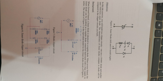

些 Figure 4: Zener Diode (left) and it's model (right) Obiectives: In this lab exercise, you will build two clipper circuits - one use a IN uses IN4732A zener diode. The characteristics of Zener diodes compare to diode will be compared in the clipper circuits you built. 4001 diode and another Background; When forward biased, a Zener diode is identical to a regular diode. When reverse biased, the Zener diode can be modeled as a regular diode connected backwards with a bias supply in series. The circuit of Figure 5 is the equivalent model for the Zener diode circuit of Figure 6. DIODE1 C-1.0 nF R10 kOhm V AC Figure 5 :Diode clipper circuit DIODE V AC RI C-10 n Figure 6: Zener diode clipper circuit
Shift Fn Ctrl Instruments and components 1. IN4001 diode - 1 pcs 2. IN4732A diode -1 pes 3. 470 2-1 pcs 4. 10k 2-1 pes 5. Crocodile clip cable 6. DC Power supply 7. Oscilloscope with 2 probes with build-in function generator or 8. Oscilloscope with 2 probes with separate unit Function Generator 1 . By using 1 N4001 diode, 470 Ω and 10k Ω resistor, construct a clipper circuit as shown in Figure 7 2. Set your power supply to output 4.1 V that will be used as bias in this circuit. 3. Ensure your function generator is set to high impedance (or Hi-2) output. 4. Set your function generator to generate RAMP waveform to output a-2.5 V to +2.5 V rise over 5 ms. Feed the waveform to the clipper circuit as V(t) 5. Connect channel 1 of the Oscilloscope to V(t) and channel 2 to the Vo(t). 6. Set the horizontal scale of the scope to 200 ms/div and vertical scale to 5 V/div 7. Draw the waveforms displayed on the scope to your TMA. 8. Next, remove diode IN4001 and the DC Power Supply. Replace it with IN4732A as shown in Figure 8. 9. Under the same settings on the scope and function generator, draw the new waveform displayed on the scope to your TMA. 10. Overlay both waveforms in this lab into 1 single graph below Resistor1 R 470 Ohm Diode 1N4001 AC Resistor2 R-10kOhm Vo V1 (n. +LDC ÷ Vdc-4.1 V Figure 7: Diode clipper circuit.
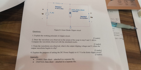
Resistor1 R-470 Ohm ADS Diode Model 1N4732A Resistor2 Vo R 10kOhm Figure 8: Zener Diode Clipper circuit xioh Questions 1. Explain the working principle of clipper circuit. 2. Draw the waveform you observed on the screen of the scope in step 9 and 11 above. [5 marks (-28 Compare the waveform observed with the simulated results. [5 marks] 3. From the waveform you observed, what is the output clipping voltages and Vi where the output waveform begins to clip? 5 marks] 4. Explain the purpose of setting the DC Power Supply to 4.1 V in the diode clipper circuit? 5 marks) Appendix 1N4001 Data sheet-attached in a separate file. IN4732A Data sheet- attached in a separate file. ·
Homework Answers


Add Answer to:
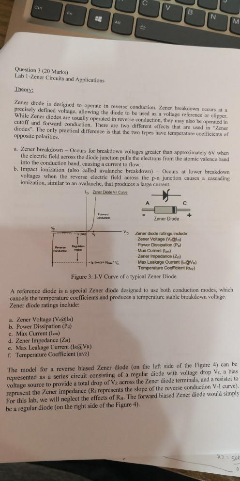
Ctri Question 3 (20 Marks) Lab 1-Zener Circuits and Applications Theory: Zener diode is designed ...
4. Design a clamp circuit to clamp the negative extreme of a periodic input waveform of 10 sin(100πt)V to −5 V. Use 1 diode, 1 Zener diode, 1 resistor, and 1 capacitor of suitable values. Provide foll...
4. Design a clamp circuit to clamp the negative extreme of a periodic input waveform of 10 sin(100πt)V to −5 V. Use 1 diode, 1 Zener diode, 1 resistor, and 1 capacitor of suitable values. Provide following minimum ratings of the selected components. (a) Diode - Maximum reverse voltage, peak forward current (b) Zener - Zener voltage, Zener current (c) Resistor - Resistance, power rating (d) capacitor - capacitance, Maximum voltage Assume a 0.6 V forward drop for all diodes...
that's all information it gives A zener-diode voltage regulator circuit is shown below. The tage V 8.0V and the zener resistance is assumed to Problem 3: (20 points) zener diode has breakdown...
 that's all information it gives
A zener-diode voltage regulator circuit is shown below. The tage V 8.0V and the zener resistance is assumed to Problem 3: (20 points) zener diode has breakdown vol be 0 ohms. The power supply voltage Vps can vary between resistance RL can vary between 100 ohms and 1 kohm. 10V and 14V and the load Ri PS 1. Find a value of Ri such that the zener diode remains properly biased over the range of...
that's all information it gives
A zener-diode voltage regulator circuit is shown below. The tage V 8.0V and the zener resistance is assumed to Problem 3: (20 points) zener diode has breakdown vol be 0 ohms. The power supply voltage Vps can vary between resistance RL can vary between 100 ohms and 1 kohm. 10V and 14V and the load Ri PS 1. Find a value of Ri such that the zener diode remains properly biased over the range of...
Problem 3: (20 points) A zener-diode voltage regulator circuit is shown belkw zener diode has breakdown voltage Vz 8.0V and the zener resistance is nsumed to be 0 ohms. The power supply voltage V...
 Problem 3: (20 points) A zener-diode voltage regulator circuit is shown belkw zener diode has breakdown voltage Vz 8.0V and the zener resistance is nsumed to be 0 ohms. The power supply voltage Vps can vary between 10V and 14V and the lod resistance Ri can vary between 100 ohms and 1 kohm, 圧 1. Find a value of R such that the zener diode remains properly biased over the range of variation of Vps and RI (hint: the minimum...
1. All of these diodes have a reverse breakdown voltage: Silicon switching diode, zener diode, schottky...
 1. All of these diodes have a reverse breakdown voltage: Silicon switching diode, zener diode, schottky diode and a light emitting diode. I or F (circle one) 2. Circle the correct statement(s) based on the following information: if you supply a 1Vp. 1KHz sine wave to a circuit with only passive elements: a) You will never measure a voltage above 1Vp b) You will always measure a voltage above 1Vp. c) You will sometimes measure a voltage above 1Vp. d)...
5. A light emitting diode (LED) is a diode that lights up when a current flows across it. The sym...
 5. A light emitting diode (LED) is a diode that lights up when a current flows across it. The symbol for an LED is shown below (sometimes wiggly arrows are used to represent the light instead.) For this question we will assume we are working with LEDs that have a turn-on voltage of VoN-1V and a reverse breakdown voltage of VBR-8V a. You hook up a single LED to a power supply that can put out vol tage from -10...
1. A star connected secondary of a 60 Hz 3-phase transformer, as shown in Fig. 3, is supplying a ...
 1. A star connected secondary of a 60 Hz 3-phase transformer, as shown in Fig. 3, is supplying a 3-phase HW uncontrolled rectifier loaded with a pure 10 Ω resistor. The fuse Fy is open circuit. L. Determine the conduction periods of the diodes ii Draw the waveform of the output voltage. F1 D D and D in msec. phase A iii. Calculate the secondary line voltage if the average iv. Draw the waveforms of the supply currents i, and...
ans NO 2 TEE208/05 Question 1 (20 marks) (a) Sketch and label the I-V curves of:...
 ans NO 2 TEE208/05 Question 1 (20 marks) (a) Sketch and label the I-V curves of: () a real germanium diode with forward voltage of 0.3V. 4 marks (i) a real sillcon zener diode with zener voltage of 4.7V. [4 marks] 4 marks] List two breakdown mechanisms for a zener diode. (b) (c) Rectifiers convert alternating current (AC) into direct current (DC). () Sketch and label the circuit of a simple half-wave rectifier. [3 marks] (U) Explain two differences between...
3. For the regulated power supply shown in Figure 5-3, which is a full-wave bridge rectifier...
 3. For the regulated power supply shown in Figure 5-3, which is a full-wave bridge rectifier containing ter combined with a Zener diode voltage regulator, determine the load voltage VI, load current Ir, source current Is, Zener current Iz and the ripple voltage at the input and output of the regulator, and r(p-p)y respectively, and the ripple frequency fr a fil- VL Ir. Is Iz=. (d-4)1a Ur(p-P) Is V' 1N4002GP Vout = VL + Iz IL 100 V2 120 V...
Could younplease help me go through the solution of this question. b c d expecting a detailed exp...
 could younplease help me go through the solution of this question.
b c d
expecting a detailed explanation.
Thanks
5. A circuit co nsists of a diode, resistor and capacitor as shown in Figure 11 and is driven by a 50 Hz sinusoidal waveform. Assume that the diode has a forward threshold voltage of 0.7 V an "on resistance" of 0.1 2 and a reverse breakdown of 20 V Sketch the I - V behaviour of the diode. (a) 13...
could younplease help me go through the solution of this question.
b c d
expecting a detailed explanation.
Thanks
5. A circuit co nsists of a diode, resistor and capacitor as shown in Figure 11 and is driven by a 50 Hz sinusoidal waveform. Assume that the diode has a forward threshold voltage of 0.7 V an "on resistance" of 0.1 2 and a reverse breakdown of 20 V Sketch the I - V behaviour of the diode. (a) 13...
Design a FULL WAVE BRIDGE RECTIFIER circuit that will: Take 120volts ac, 60 hz, sinusoidal waveform...
 Design a FULL WAVE BRIDGE RECTIFIER circuit that will:
Take 120volts ac, 60 hz, sinusoidal waveform and convert
it to a “regulated “dc value
giving 12 volts +, - 1 volt across a 2000-ohm output
load resistor with no more than 2%
ripple voltage.
You may assume:
a. An ideal power transformer as discussed in class.
b. For hand computations, you must assume a diode given by
Figure 4.8 page 185.
c. A filter capacitor sized per the textbook equation...
Design a FULL WAVE BRIDGE RECTIFIER circuit that will:
Take 120volts ac, 60 hz, sinusoidal waveform and convert
it to a “regulated “dc value
giving 12 volts +, - 1 volt across a 2000-ohm output
load resistor with no more than 2%
ripple voltage.
You may assume:
a. An ideal power transformer as discussed in class.
b. For hand computations, you must assume a diode given by
Figure 4.8 page 185.
c. A filter capacitor sized per the textbook equation...
 that's all information it gives
A zener-diode voltage regulator circuit is shown below. The tage V 8.0V and the zener resistance is assumed to Problem 3: (20 points) zener diode has breakdown vol be 0 ohms. The power supply voltage Vps can vary between resistance RL can vary between 100 ohms and 1 kohm. 10V and 14V and the load Ri PS 1. Find a value of Ri such that the zener diode remains properly biased over the range of...
that's all information it gives
A zener-diode voltage regulator circuit is shown below. The tage V 8.0V and the zener resistance is assumed to Problem 3: (20 points) zener diode has breakdown vol be 0 ohms. The power supply voltage Vps can vary between resistance RL can vary between 100 ohms and 1 kohm. 10V and 14V and the load Ri PS 1. Find a value of Ri such that the zener diode remains properly biased over the range of...
 Problem 3: (20 points) A zener-diode voltage regulator circuit is shown belkw zener diode has breakdown voltage Vz 8.0V and the zener resistance is nsumed to be 0 ohms. The power supply voltage Vps can vary between 10V and 14V and the lod resistance Ri can vary between 100 ohms and 1 kohm, 圧 1. Find a value of R such that the zener diode remains properly biased over the range of variation of Vps and RI (hint: the minimum...
 1. All of these diodes have a reverse breakdown voltage: Silicon switching diode, zener diode, schottky diode and a light emitting diode. I or F (circle one) 2. Circle the correct statement(s) based on the following information: if you supply a 1Vp. 1KHz sine wave to a circuit with only passive elements: a) You will never measure a voltage above 1Vp b) You will always measure a voltage above 1Vp. c) You will sometimes measure a voltage above 1Vp. d)...
 5. A light emitting diode (LED) is a diode that lights up when a current flows across it. The symbol for an LED is shown below (sometimes wiggly arrows are used to represent the light instead.) For this question we will assume we are working with LEDs that have a turn-on voltage of VoN-1V and a reverse breakdown voltage of VBR-8V a. You hook up a single LED to a power supply that can put out vol tage from -10...
 1. A star connected secondary of a 60 Hz 3-phase transformer, as shown in Fig. 3, is supplying a 3-phase HW uncontrolled rectifier loaded with a pure 10 Ω resistor. The fuse Fy is open circuit. L. Determine the conduction periods of the diodes ii Draw the waveform of the output voltage. F1 D D and D in msec. phase A iii. Calculate the secondary line voltage if the average iv. Draw the waveforms of the supply currents i, and...
 ans NO 2 TEE208/05 Question 1 (20 marks) (a) Sketch and label the I-V curves of: () a real germanium diode with forward voltage of 0.3V. 4 marks (i) a real sillcon zener diode with zener voltage of 4.7V. [4 marks] 4 marks] List two breakdown mechanisms for a zener diode. (b) (c) Rectifiers convert alternating current (AC) into direct current (DC). () Sketch and label the circuit of a simple half-wave rectifier. [3 marks] (U) Explain two differences between...
 3. For the regulated power supply shown in Figure 5-3, which is a full-wave bridge rectifier containing ter combined with a Zener diode voltage regulator, determine the load voltage VI, load current Ir, source current Is, Zener current Iz and the ripple voltage at the input and output of the regulator, and r(p-p)y respectively, and the ripple frequency fr a fil- VL Ir. Is Iz=. (d-4)1a Ur(p-P) Is V' 1N4002GP Vout = VL + Iz IL 100 V2 120 V...
 could younplease help me go through the solution of this question.
b c d
expecting a detailed explanation.
Thanks
5. A circuit co nsists of a diode, resistor and capacitor as shown in Figure 11 and is driven by a 50 Hz sinusoidal waveform. Assume that the diode has a forward threshold voltage of 0.7 V an "on resistance" of 0.1 2 and a reverse breakdown of 20 V Sketch the I - V behaviour of the diode. (a) 13...
could younplease help me go through the solution of this question.
b c d
expecting a detailed explanation.
Thanks
5. A circuit co nsists of a diode, resistor and capacitor as shown in Figure 11 and is driven by a 50 Hz sinusoidal waveform. Assume that the diode has a forward threshold voltage of 0.7 V an "on resistance" of 0.1 2 and a reverse breakdown of 20 V Sketch the I - V behaviour of the diode. (a) 13...
 Design a FULL WAVE BRIDGE RECTIFIER circuit that will:
Take 120volts ac, 60 hz, sinusoidal waveform and convert
it to a “regulated “dc value
giving 12 volts +, - 1 volt across a 2000-ohm output
load resistor with no more than 2%
ripple voltage.
You may assume:
a. An ideal power transformer as discussed in class.
b. For hand computations, you must assume a diode given by
Figure 4.8 page 185.
c. A filter capacitor sized per the textbook equation...
Design a FULL WAVE BRIDGE RECTIFIER circuit that will:
Take 120volts ac, 60 hz, sinusoidal waveform and convert
it to a “regulated “dc value
giving 12 volts +, - 1 volt across a 2000-ohm output
load resistor with no more than 2%
ripple voltage.
You may assume:
a. An ideal power transformer as discussed in class.
b. For hand computations, you must assume a diode given by
Figure 4.8 page 185.
c. A filter capacitor sized per the textbook equation...
Most questions answered within 3 hours.
-
You have a 825.3 mL sample of 2.754 M HA (Ka =
4.49⋅10−4). Calculate the pH...
asked 51 minutes ago -
The blues made its way into many kinds of music. Eric Clapton,
The Beatles, and Elvis...
asked 2 hours ago -
8. A wave in a string has a wave function given by: y (x, t) =...
asked 1 hour ago -
If you’re standing at the bottom of a hill and asked to evaluate
it while being...
asked 3 hours ago -
1. Which region has taken the lead in the world of
e-waste handling?
a) European Union...
asked 3 hours ago -
A 8.15- g bullet from a 9-mm pistol has a velocity of 366.0 m/s.
It strikes...
asked 5 hours ago -
The outstanding bonds of Alpha Extracts have a yield to maturity
of 7.4 percent and a...
asked 5 hours ago -
The Problem: The Case of the Harmonizing Vacations
Your CEO is exploring partnering with a European...
asked 6 hours ago -
A chemical equation is balanced by adding coefficients in front
of some formulas so that the...
asked 6 hours ago -
From the literature (reference your sources): What are the
lattice parameters of calcite and aragonite? Why...
asked 7 hours ago -
Your system is rejecting the question am asking which is
preceded by a case study. It...
asked 7 hours ago -
3. On January 2, 2000, Larry creates a trust with himself as
trustee. Larry as trustee...
asked 7 hours ago