
Homework Answers
If you like my work please upvote ?
 c)
c)
C)ii)
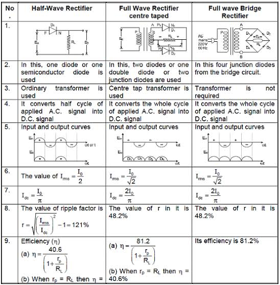
Consider half wave rectifier and bridge rectifier
Add Answer to:
ans NO 2 TEE208/05 Question 1 (20 marks) (a) Sketch and label the I-V curves of:...
Ctri Question 3 (20 Marks) Lab 1-Zener Circuits and Applications Theory: Zener diode is designed ...
 Ctri Question 3 (20 Marks) Lab 1-Zener Circuits and Applications Theory: Zener diode is designed to operate in reverse conduction. Zener breakdown occurs at a precisely defined voltage, allowing the diode to be used as a voltage reference or clipper. While Zener diodes are usually operated in reverse conduction, they may also be operated in cutoff and forward conduction. There are two different effects that are used in "Zener diodes". The only practical difference is that the two types have...
Question 1 (a) Draw the actual OR the idealized i-v characteristics of a MOSFET. Propery label th...
 Question 1 (a) Draw the actual OR the idealized i-v characteristics of a MOSFET. Propery label the drawn graph. [4 marks] (b) Name any two types of diodes AND any two types of thyristors. [4 marks] (c) Find the following values for the periodic current output of a diode rectifier with square voltage input and resistive load. The output is shown in the figure below. (i) Average (ii) Root mean square (RMS) (ii) RMS of the 1st harmonic (iv) Total...
Question 1 (a) Draw the actual OR the idealized i-v characteristics of a MOSFET. Propery label...
 Question 1 (a) Draw the actual OR the idealized i-v characteristics of a MOSFET. Propery label the drawn graph. [4 marks] (b) Name any two types of diodes AND any two types of thyristors. [4 marks] (c) Find the following values for the periodic current output of a diode rectifier with square voltage input and resistive load. The output is shown in the figure below. (i) Average (ii) Root mean square (RMS) (ii) RMS of the 1st harmonic (iv) Total...
please answer these 2 questions please i really need help with them for review thank you...
 please answer these 2 questions please i really need
help with them for review thank you so much for your help a quick
response will be greatly appreciated as i am studying now and have
a test tomorrow thank you so much
7. A fixed input voltage, variable load resistance, Zener diode regulator circuit has the following known values: Vi = 20.7V, Vz = 7.5V, PzM = 300mW Calculate the series resistance required if a load resistance of 4700 causes...
please answer these 2 questions please i really need
help with them for review thank you so much for your help a quick
response will be greatly appreciated as i am studying now and have
a test tomorrow thank you so much
7. A fixed input voltage, variable load resistance, Zener diode regulator circuit has the following known values: Vi = 20.7V, Vz = 7.5V, PzM = 300mW Calculate the series resistance required if a load resistance of 4700 causes...
Question 1 (25 marks) a) A full wave rectifier has 40V peak secondary voltage, 2,000uF capacitor...
 Question 1 (25 marks) a) A full wave rectifier has 40V peak secondary voltage, 2,000uF capacitor and 1022 load. You may take the line frequency as 50Hz and voltage drop across a diode as 0.7V. i. Calculate the peak dc voltage (VA). (2 marks) ii. Calculate the dc load voltage (Vdcloed). (4 marks) iii. Calculate the ripple voltage (AVLoad). (4 marks) b) The capacitance, inductance and load resistance of a Buck step-down dc-to-dc converter are 1.0uF, 10uH and 20.022 respectively....
Design a FULL WAVE BRIDGE RECTIFIER circuit that will: Take 120volts ac, 60 hz, sinusoidal waveform...
 Design a FULL WAVE BRIDGE RECTIFIER circuit that will:
Take 120volts ac, 60 hz, sinusoidal waveform and convert
it to a “regulated “dc value
giving 12 volts +, - 1 volt across a 2000-ohm output
load resistor with no more than 2%
ripple voltage.
You may assume:
a. An ideal power transformer as discussed in class.
b. For hand computations, you must assume a diode given by
Figure 4.8 page 185.
c. A filter capacitor sized per the textbook equation...
Design a FULL WAVE BRIDGE RECTIFIER circuit that will:
Take 120volts ac, 60 hz, sinusoidal waveform and convert
it to a “regulated “dc value
giving 12 volts +, - 1 volt across a 2000-ohm output
load resistor with no more than 2%
ripple voltage.
You may assume:
a. An ideal power transformer as discussed in class.
b. For hand computations, you must assume a diode given by
Figure 4.8 page 185.
c. A filter capacitor sized per the textbook equation...
02 +Vo D3 Rgare 18 Circuit for Problem 1 Analysis 1. Copy the circuit of Figure 1.8 and sketch the ow of pesitive curment throughout the entire circuit for o>0. Repeat for n ce 2....
 02 +Vo D3 Rgare 18 Circuit for Problem 1 Analysis 1. Copy the circuit of Figure 1.8 and sketch the ow of pesitive curment throughout the entire circuit for o>0. Repeat for n ce 2. Plot two periods of nlt) and s) for each of the thee input wave shown in Figune 17 on page 37 fom output t (a) Feak value, and b) Eflective DC value, also known as RMS value NotTE These and are therefore optional 4. Determine...
Question 4. (a) A full-wave bridge rectifier power supply is powered from the secondary of a...
 Question 4. (a) A full-wave bridge rectifier power supply is powered from the secondary of a transformer which has a rms secondary voltage of 15.6V. The primary of the transformer is connected to a 50Hz, 230VRMS power supply. A 2700uF filter capacitor is used. A current of 1.5 Amp is drawn from the supply. (i) Sketch a schematic diagram of the setup. (ii) Calculate the mean de output voltage. Assume each power diode has a forward voltage drop of 1...
QUESTION 2 [20 marks] (i) [10 marks] A 120-V dc generator energizes a motor whose coil...
 QUESTION 2 [20 marks] (i) [10 marks] A 120-V dc generator energizes a motor whose coil has an inductance of 50 H in series with a resistance of 100 2. A field discharge resistor of 400 2 is connected in parallel with the motor to avoid damage to the motor, as shown in Figure 3. Find the current through the discharge resistor 100 ms after the breaker is tripped. (The circuit breaker has been in the closed position for a...
( Q2) Marks 14+14+6 In Fig 2 L1 mH and R-0.001 2 Vac 60 V. Square wave switching is used with switching frequency of 300 Hz and 50% duty cycle. Assume ideal switches and ideal diodes. Switches S1, S...
 ( Q2) Marks 14+14+6 In Fig 2 L1 mH and R-0.001 2 Vac 60 V. Square wave switching is used with switching frequency of 300 Hz and 50% duty cycle. Assume ideal switches and ideal diodes. Switches S1, S2. S3 and S4 are IGBTs/MOSFETs and Diode D and D2, D3 and D4 are antiparallel body diodes of these devices.. At steady state Sketch the gate signal for S1, VAN and o. For each region, indicate the conducting devices, by clearly...
 Ctri Question 3 (20 Marks) Lab 1-Zener Circuits and Applications Theory: Zener diode is designed to operate in reverse conduction. Zener breakdown occurs at a precisely defined voltage, allowing the diode to be used as a voltage reference or clipper. While Zener diodes are usually operated in reverse conduction, they may also be operated in cutoff and forward conduction. There are two different effects that are used in "Zener diodes". The only practical difference is that the two types have...
 Question 1 (a) Draw the actual OR the idealized i-v characteristics of a MOSFET. Propery label the drawn graph. [4 marks] (b) Name any two types of diodes AND any two types of thyristors. [4 marks] (c) Find the following values for the periodic current output of a diode rectifier with square voltage input and resistive load. The output is shown in the figure below. (i) Average (ii) Root mean square (RMS) (ii) RMS of the 1st harmonic (iv) Total...
 Question 1 (a) Draw the actual OR the idealized i-v characteristics of a MOSFET. Propery label the drawn graph. [4 marks] (b) Name any two types of diodes AND any two types of thyristors. [4 marks] (c) Find the following values for the periodic current output of a diode rectifier with square voltage input and resistive load. The output is shown in the figure below. (i) Average (ii) Root mean square (RMS) (ii) RMS of the 1st harmonic (iv) Total...
 please answer these 2 questions please i really need
help with them for review thank you so much for your help a quick
response will be greatly appreciated as i am studying now and have
a test tomorrow thank you so much
7. A fixed input voltage, variable load resistance, Zener diode regulator circuit has the following known values: Vi = 20.7V, Vz = 7.5V, PzM = 300mW Calculate the series resistance required if a load resistance of 4700 causes...
please answer these 2 questions please i really need
help with them for review thank you so much for your help a quick
response will be greatly appreciated as i am studying now and have
a test tomorrow thank you so much
7. A fixed input voltage, variable load resistance, Zener diode regulator circuit has the following known values: Vi = 20.7V, Vz = 7.5V, PzM = 300mW Calculate the series resistance required if a load resistance of 4700 causes...
 Question 1 (25 marks) a) A full wave rectifier has 40V peak secondary voltage, 2,000uF capacitor and 1022 load. You may take the line frequency as 50Hz and voltage drop across a diode as 0.7V. i. Calculate the peak dc voltage (VA). (2 marks) ii. Calculate the dc load voltage (Vdcloed). (4 marks) iii. Calculate the ripple voltage (AVLoad). (4 marks) b) The capacitance, inductance and load resistance of a Buck step-down dc-to-dc converter are 1.0uF, 10uH and 20.022 respectively....
 Design a FULL WAVE BRIDGE RECTIFIER circuit that will:
Take 120volts ac, 60 hz, sinusoidal waveform and convert
it to a “regulated “dc value
giving 12 volts +, - 1 volt across a 2000-ohm output
load resistor with no more than 2%
ripple voltage.
You may assume:
a. An ideal power transformer as discussed in class.
b. For hand computations, you must assume a diode given by
Figure 4.8 page 185.
c. A filter capacitor sized per the textbook equation...
Design a FULL WAVE BRIDGE RECTIFIER circuit that will:
Take 120volts ac, 60 hz, sinusoidal waveform and convert
it to a “regulated “dc value
giving 12 volts +, - 1 volt across a 2000-ohm output
load resistor with no more than 2%
ripple voltage.
You may assume:
a. An ideal power transformer as discussed in class.
b. For hand computations, you must assume a diode given by
Figure 4.8 page 185.
c. A filter capacitor sized per the textbook equation...
 02 +Vo D3 Rgare 18 Circuit for Problem 1 Analysis 1. Copy the circuit of Figure 1.8 and sketch the ow of pesitive curment throughout the entire circuit for o>0. Repeat for n ce 2. Plot two periods of nlt) and s) for each of the thee input wave shown in Figune 17 on page 37 fom output t (a) Feak value, and b) Eflective DC value, also known as RMS value NotTE These and are therefore optional 4. Determine...
 Question 4. (a) A full-wave bridge rectifier power supply is powered from the secondary of a transformer which has a rms secondary voltage of 15.6V. The primary of the transformer is connected to a 50Hz, 230VRMS power supply. A 2700uF filter capacitor is used. A current of 1.5 Amp is drawn from the supply. (i) Sketch a schematic diagram of the setup. (ii) Calculate the mean de output voltage. Assume each power diode has a forward voltage drop of 1...
 QUESTION 2 [20 marks] (i) [10 marks] A 120-V dc generator energizes a motor whose coil has an inductance of 50 H in series with a resistance of 100 2. A field discharge resistor of 400 2 is connected in parallel with the motor to avoid damage to the motor, as shown in Figure 3. Find the current through the discharge resistor 100 ms after the breaker is tripped. (The circuit breaker has been in the closed position for a...
 ( Q2) Marks 14+14+6 In Fig 2 L1 mH and R-0.001 2 Vac 60 V. Square wave switching is used with switching frequency of 300 Hz and 50% duty cycle. Assume ideal switches and ideal diodes. Switches S1, S2. S3 and S4 are IGBTs/MOSFETs and Diode D and D2, D3 and D4 are antiparallel body diodes of these devices.. At steady state Sketch the gate signal for S1, VAN and o. For each region, indicate the conducting devices, by clearly...
Most questions answered within 3 hours.
-
Consider the reaction, C3 H8 + O2 --> CO2 + H2O. How many
moles of O2...
asked 22 minutes ago -
You and your opponent both roll a fair die. If you both roll the
same number,...
asked 40 minutes ago -
In a study of the accuracy of fast food drive-through orders,
Restaurant A had 257 accurate...
asked 39 minutes ago -
Identify and describe in detail the four categories of
institutions that could be included in a...
asked 45 minutes ago -
In python
class Customer:
def __init__(self, customer_id, last_name, first_name, phone_number, address):
self._customer_id = int(customer_id)
self._last_name =...
asked 53 minutes ago -
What is an example of a limitation in implementing a new
ERP system and how it...
asked 48 minutes ago -
In a section of 9.7cm of an artery with a radius of 2.6mm there
is a...
asked 49 minutes ago -
the two carboxylic acid groups of aspartic acid have different
acidities with pKa values of 2.1...
asked 53 minutes ago -
Would CuCO3 aqueous salt combined with calcium chloride
form a solid precipitate? If so, what would...
asked 52 minutes ago -
How do ECM Solutions assist in embedding a culture of continuous
improvement in an organization? (Project...
asked 1 hour ago -
Directions
These directions introduce the idea of Essential Questions.
Since this may be a new concept...
asked 1 hour ago -
1.b. Fiscal policy is said to suffer from ‘crowding out’.
Explain what this means and why...
asked 1 hour ago