
Homework Answers


Add Answer to:
Problem 4 For the shaft below, (a) Calculate the normal and shear stresses at elements A...
The solid shaft is sujected to a torque and vertical force as shown. Calculate the stresses...
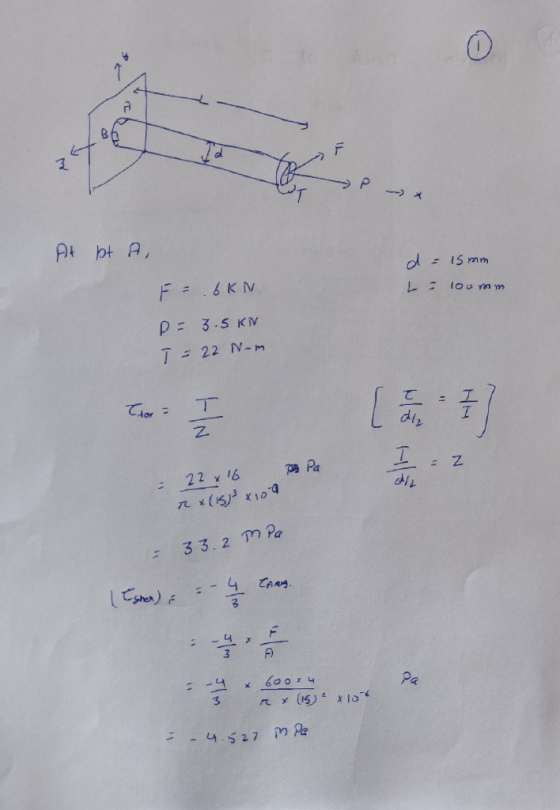
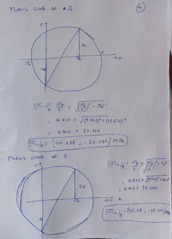
 The solid shaft is sujected to a torque and vertical force as shown. Calculate the stresses acting at point A and draw Mohr's circle. Then, determine: (a) the principal stresses, (b) the maximum in-plane shear stress and average normal stress. 450 mm r=25 mm Specify the orientation and sketch the element in each case. 245 N-m HintForcirculararea: Solution: 1x=1,-, J=2. 800 N
1-Determine the stresses at points K and H for the following bar consider shear stresses as...
 1-Determine the stresses at points K and H for the following bar consider shear stresses as well, and second by using Mohr's circle determine principal stresses and maximum shear stress at point H. Radius of the bar is 0.2m b 60 mm a-50 mm Pl 15 kN
3. The propeller shaft of the tugboat is subjected to the compressive force and torque shown....
 3. The propeller shaft of the tugboat is subjected to the compressive force and torque shown. The shaft has an inner diameter of 125 mm and an outer diameter of 175 mm. (20 pts) 0410 KN 2 kNm Determine the following at point A located on the outer surface: avg. TMIP, 8s Principal stresses and Op c Draw Mohr's circle d Draw principal stress and maximum in plane shear stress elements
Q3. (30 points) For the state of plane stress shown, Stresses, σ. σ2 (b) the orientation of the p...
 please help me solve this whole mechanical design
problem
thanks
Q3. (30 points) For the state of plane stress shown, Stresses, σ. σ2 (b) the orientation of the principal stresses, s, (c) the maximum in plane shearing stress, Tmar and (d) its orientation, p. (e) the normal stress at the plane of maximum shear stress, (1) sketch of the rotated plane element for the principal stresses and the rotated plane element for maximum shear stress similar to figure 1, below...
please help me solve this whole mechanical design
problem
thanks
Q3. (30 points) For the state of plane stress shown, Stresses, σ. σ2 (b) the orientation of the principal stresses, s, (c) the maximum in plane shearing stress, Tmar and (d) its orientation, p. (e) the normal stress at the plane of maximum shear stress, (1) sketch of the rotated plane element for the principal stresses and the rotated plane element for maximum shear stress similar to figure 1, below...
4. (a) Find the normal and shear stresses on the plane indicated on the element. (6)...
 4. (a) Find the normal and shear stresses on the plane indicated on the element. (6) Sketch Mohr's circle. (b) Determine the principal planes and the principal stresses using Mohr's circle approach. Sketch the results. (25 points) .80 M Pa 120 MPa •40 MPa
2) Two forces P- 18 kN and F 15 kN are applied to the shaft with a diameter of D - 40 mm, as shown. A torque T= 750 N·m is also applied on the free end of the shaft. Determine the location and magnit...
 2) Two forces P- 18 kN and F 15 kN are applied to the shaft with a diameter of D - 40 mm, as shown. A torque T= 750 N·m is also applied on the free end of the shaft. Determine the location and magnitudes of maximum normal and shear stresses developed in the shaft. For full credit, show your work (40 points). T IP
2) Two forces P- 18 kN and F 15 kN are applied to the shaft...
2) Two forces P- 18 kN and F 15 kN are applied to the shaft with a diameter of D - 40 mm, as shown. A torque T= 750 N·m is also applied on the free end of the shaft. Determine the location and magnitudes of maximum normal and shear stresses developed in the shaft. For full credit, show your work (40 points). T IP
2) Two forces P- 18 kN and F 15 kN are applied to the shaft...
Problem 2: A circular shaft transmits power as shown with pulley loads. The shaft carries a...
 Problem 2: A circular shaft transmits power as shown with pulley loads. The shaft carries a torque, bending, shear and axial loads. Draw LVM diagram to find Mmax and Vmax. Show all loads (moments and forces) on the circular x-section of the shaft below. Use double arrows for moments. Compute shear and normal stresses and show them on the same section. Create stress elements for points A and B of the section. Combine the stresses and compute Tmax (Tresca) and...
Problem #1 For the simply supported beam given below. E-200 GPa and u-o3. 18 kN 24...
 Problem #1 For the simply supported beam given below. E-200 GPa and u-o3. 18 kN 24 kN 2.4 m 4.0 m 1.8 m 150 mm 100 mm E.N.A 250 mm 200 mm Draw the shear diagram and the moment diagram For the location halfway between the right support and the 24 kN concentrated load, draw Mohr's circle for the stress states at points "a" "b", and "c" on the same axes a. b. c. For the location at midspan, draw...
Problem #4: The frame supports the triangular distributed load shown Use Mohr's circle to determine the normal and shear stresses at point E that act perpendicular and parallel, respectively, to...
 Problem #4: The frame supports the triangular distributed load shown Use Mohr's circle to determine the normal and shear stresses at point E that act perpendicular and parallel, respectively, to the grains. The grains at this point make an angle of 45° with the horizontal as shown. Point C is the pin support. 900 N/m 35 75 mmi 200 mm 2.4 m 0.6 m 100 mm 3 m 45° 50 mm 30 mm 1.5 m 100 mm
Problem #4: The...
Problem #4: The frame supports the triangular distributed load shown Use Mohr's circle to determine the normal and shear stresses at point E that act perpendicular and parallel, respectively, to the grains. The grains at this point make an angle of 45° with the horizontal as shown. Point C is the pin support. 900 N/m 35 75 mmi 200 mm 2.4 m 0.6 m 100 mm 3 m 45° 50 mm 30 mm 1.5 m 100 mm
Problem #4: The...
Problem 2: A circular shaft transmits power as shown with pulley loads. The shaft carries a...
 Problem 2: A circular shaft transmits power as shown with pulley loads. The shaft carries a torque, bending, shear and axial loads. Draw LVM diagram to find Mmax and Vmax. Show all loads (moments and forces) on the circular x-section of the shaft below. Use double arrows for moments. Compute shear and normal stresses and show them on the same section. Create stress elements for points A and B of the section. Combine the stresses and compute Cuau (Tresca) and...
 The solid shaft is sujected to a torque and vertical force as shown. Calculate the stresses acting at point A and draw Mohr's circle. Then, determine: (a) the principal stresses, (b) the maximum in-plane shear stress and average normal stress. 450 mm r=25 mm Specify the orientation and sketch the element in each case. 245 N-m HintForcirculararea: Solution: 1x=1,-, J=2. 800 N
 1-Determine the stresses at points K and H for the following bar consider shear stresses as well, and second by using Mohr's circle determine principal stresses and maximum shear stress at point H. Radius of the bar is 0.2m b 60 mm a-50 mm Pl 15 kN
 3. The propeller shaft of the tugboat is subjected to the compressive force and torque shown. The shaft has an inner diameter of 125 mm and an outer diameter of 175 mm. (20 pts) 0410 KN 2 kNm Determine the following at point A located on the outer surface: avg. TMIP, 8s Principal stresses and Op c Draw Mohr's circle d Draw principal stress and maximum in plane shear stress elements
 please help me solve this whole mechanical design
problem
thanks
Q3. (30 points) For the state of plane stress shown, Stresses, σ. σ2 (b) the orientation of the principal stresses, s, (c) the maximum in plane shearing stress, Tmar and (d) its orientation, p. (e) the normal stress at the plane of maximum shear stress, (1) sketch of the rotated plane element for the principal stresses and the rotated plane element for maximum shear stress similar to figure 1, below...
please help me solve this whole mechanical design
problem
thanks
Q3. (30 points) For the state of plane stress shown, Stresses, σ. σ2 (b) the orientation of the principal stresses, s, (c) the maximum in plane shearing stress, Tmar and (d) its orientation, p. (e) the normal stress at the plane of maximum shear stress, (1) sketch of the rotated plane element for the principal stresses and the rotated plane element for maximum shear stress similar to figure 1, below...
 4. (a) Find the normal and shear stresses on the plane indicated on the element. (6) Sketch Mohr's circle. (b) Determine the principal planes and the principal stresses using Mohr's circle approach. Sketch the results. (25 points) .80 M Pa 120 MPa •40 MPa
 2) Two forces P- 18 kN and F 15 kN are applied to the shaft with a diameter of D - 40 mm, as shown. A torque T= 750 N·m is also applied on the free end of the shaft. Determine the location and magnitudes of maximum normal and shear stresses developed in the shaft. For full credit, show your work (40 points). T IP
2) Two forces P- 18 kN and F 15 kN are applied to the shaft...
2) Two forces P- 18 kN and F 15 kN are applied to the shaft with a diameter of D - 40 mm, as shown. A torque T= 750 N·m is also applied on the free end of the shaft. Determine the location and magnitudes of maximum normal and shear stresses developed in the shaft. For full credit, show your work (40 points). T IP
2) Two forces P- 18 kN and F 15 kN are applied to the shaft...
 Problem 2: A circular shaft transmits power as shown with pulley loads. The shaft carries a torque, bending, shear and axial loads. Draw LVM diagram to find Mmax and Vmax. Show all loads (moments and forces) on the circular x-section of the shaft below. Use double arrows for moments. Compute shear and normal stresses and show them on the same section. Create stress elements for points A and B of the section. Combine the stresses and compute Tmax (Tresca) and...
 Problem #1 For the simply supported beam given below. E-200 GPa and u-o3. 18 kN 24 kN 2.4 m 4.0 m 1.8 m 150 mm 100 mm E.N.A 250 mm 200 mm Draw the shear diagram and the moment diagram For the location halfway between the right support and the 24 kN concentrated load, draw Mohr's circle for the stress states at points "a" "b", and "c" on the same axes a. b. c. For the location at midspan, draw...
 Problem #4: The frame supports the triangular distributed load shown Use Mohr's circle to determine the normal and shear stresses at point E that act perpendicular and parallel, respectively, to the grains. The grains at this point make an angle of 45° with the horizontal as shown. Point C is the pin support. 900 N/m 35 75 mmi 200 mm 2.4 m 0.6 m 100 mm 3 m 45° 50 mm 30 mm 1.5 m 100 mm
Problem #4: The...
Problem #4: The frame supports the triangular distributed load shown Use Mohr's circle to determine the normal and shear stresses at point E that act perpendicular and parallel, respectively, to the grains. The grains at this point make an angle of 45° with the horizontal as shown. Point C is the pin support. 900 N/m 35 75 mmi 200 mm 2.4 m 0.6 m 100 mm 3 m 45° 50 mm 30 mm 1.5 m 100 mm
Problem #4: The...
 Problem 2: A circular shaft transmits power as shown with pulley loads. The shaft carries a torque, bending, shear and axial loads. Draw LVM diagram to find Mmax and Vmax. Show all loads (moments and forces) on the circular x-section of the shaft below. Use double arrows for moments. Compute shear and normal stresses and show them on the same section. Create stress elements for points A and B of the section. Combine the stresses and compute Cuau (Tresca) and...
Most questions answered within 3 hours.
-
Kelsey Drums, Inc., is a well-established supplier of fine
percussion instruments to orchestras all over the...
asked 27 seconds ago -
In a criminal case, the state must not prove its case beyond a
reasonable doubt. T/F
asked 5 minutes ago -
5.6 dm^3 of gaseous HCl (as measured in normal conditions) is
dissolved in 100 cm^3 of...
asked 14 minutes ago -
The hammer throw is a track-and-field event in which a 7.2-kg
ball (the ''hammer''), starting from...
asked 31 minutes ago -
Evaluate a specific listening situation using the Sapir-Whorf
and Bernstein hypothesis. What was thecontext? What was...
asked 38 minutes ago -
Recall that if X is a Student’s t random variable with n df,
then by definition...
asked 56 minutes ago -
A charge of -2.95 µC is fixed in place. From a horizontal
distance of 0.0470 m,...
asked 53 minutes ago -
Consider the following information:
Your company makes widgets. You are trying to figure out what
volume...
asked 55 minutes ago -
Math 333 Plz help ASAP
The yield of a chemical process is being studied. From previous...
asked 1 hour ago -
Cobb-Douglas Preferences: Cobb-Douglas preferences on the
consump-
tion set R2+ can be represented by a utility...
asked 1 hour ago -
In your experience, what are some of the barriers to the
successful implementation of a project?...
asked 1 hour ago -
1. A normal distribution has a mean of
μ = 60 and a standard deviation
of...
asked 1 hour ago