
Homework Answers


Add Answer to:
Problem 2: For the beam shown below: 16.0 kN/m 8.0 kN/m 16.8 mm 354 mm 9.4...
For the beam shown below (neglect self-weight of the beam) 16 kN x 8 mm 19...
 For the beam shown below (neglect self-weight of the beam) 16 kN x 8 mm 19 kN 10 kN/m T 2 mm mm A4n - 3 m +3m → a. Draw the shear force and bending moment diagram. 2 mm Section X-X b. For the cross section x-x given, calculate the maximum tensile and compressive bending stress c. For the cross section X-X given, calculate the maximum shear stress
10 mm 10 mm 300 N/m 50 mm 10 mm Problem 2. Consider the beam above with the cross-section shown. ...
 please solve 1-5 and show all steps and equations used
10 mm 10 mm 300 N/m 50 mm 10 mm Problem 2. Consider the beam above with the cross-section shown. The number (300N/m) indicates the value of the load distribution at its peak. (5 pts.) Find the reactions (15 pts.) Draw the shear and moment diagrams using the graphical method. Ensure you state values of the diagrams, and type of function for lincar or higher-order segments. You can indicate all...
please solve 1-5 and show all steps and equations used
10 mm 10 mm 300 N/m 50 mm 10 mm Problem 2. Consider the beam above with the cross-section shown. The number (300N/m) indicates the value of the load distribution at its peak. (5 pts.) Find the reactions (15 pts.) Draw the shear and moment diagrams using the graphical method. Ensure you state values of the diagrams, and type of function for lincar or higher-order segments. You can indicate all...
For the beam shown in the figure below a. Draw the shear and moment diagrams for this beam
 For the beam shown in the figure below a. Draw the shear and moment diagrams for this beam b. Calculate the maximum bending stress, maximum axial stress, and maximum shear stress acting on the beam cross section c. Sketch the distributions of shear stresses and bending stresses acting on the beam cross section at the locations where these stresses are maximum.
6 kN/m 15 kN 100 mm E NA - B D 100 mm 0.8 m For...
 6 kN/m 15 kN 100 mm E NA - B D 100 mm 0.8 m For the truss system shown, a. (10 pts) Draw the shear and moment diagrams for the rectangular wooden beam shown. b. (6 pts)Determine the magnitude of the absolute maximum moment (Mmax) and its location c. (Z pts) Find the maximum bending stress in the member (max) d. (Z pts)Compute the Bending Stress at a point on the section B that is 25 mm below the...
15 kN 6 kN/m 100 mm AC E NA - B D 100 mm 0.8 m...
 15 kN 6 kN/m 100 mm AC E NA - B D 100 mm 0.8 m 2. (30pts.) For the truss system shown, a. (10 pts) Draw the shear and moment diagrams for the rectangular wooden beam shown. b. (6 pts )Determine the magnitude of the absolute maximum moment (Mmax) and its location c. (7 pts) Find the maximum bending stress in the member (max) d. (7 pts)Compute the Bending Stress at a point on the section B that is...
20 KN 3 kN/m 3 2 KN- y, 2 kN-m 12.5 mm 200 mm? Z B...
 20 KN 3 kN/m 3 2 KN- y, 2 kN-m 12.5 mm 200 mm? Z B 150 mm 121.43 mm 1.5 m 1.5 m 2.2 m 12.5 mm Part [1] (a.) Construct shear and bending moment diagrams. Show all work. Label completely. (b.) Determine the maximum value of the transverse shear force (in magnitude) and where it occurs. 'Box' answers. (c.) Determine the maximum values of the bending moment (both positive and negative) and where each occurs. 'Box' answers. Part...
SP3-4 8 kN/m q(x) = (2+2x) kN/m 2 kN/m For the beam above, find equations for...
 SP3-4 8 kN/m q(x) = (2+2x) kN/m 2 kN/m For the beam above, find equations for internal shear force and bending moment (V(x) & M(x)), draw shear and moment (V & M) diagrams, and find the maximum positive and negative (+ & shear forces and bending moments in the beam. Answers to SP3
Beam ABC as shown in figure 2 is supported as fixed at A, a cable tie...
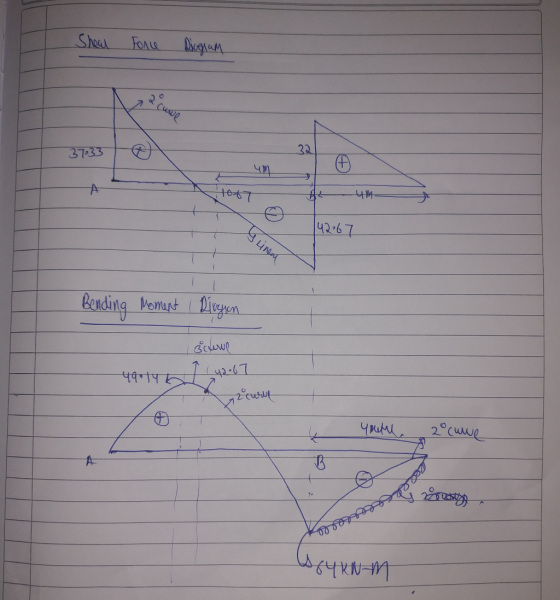
 Beam ABC as shown in figure 2 is supported as fixed at A, a cable tie at B and a spring at C carries a uniformly distributed load of 72 kN/m on member AB and a concentrated load of 54 kN on member BC. Using the flexibility method and neglect the axial effects in the bcam, (a) perform the global flexibility matrix of the beam structure, (b) calculate the rotation at B and displacement at C, (c) draw the deflection,...
A rectangular cross section at a location along a beam in bending is
 (a). A rectangular cross section at a location along a beam in bending is acted upon by a bending moment and a shear force. The cross section is \(120 \mathrm{~mm}\) wide, \(300 \mathrm{~mm}\) deep and is orientated such that it is in bending about its major axis of bending. The magnitudes of the bending moment and shear force are \(315 \mathrm{kNm}\) and \(240 \mathrm{kN}\) respectively. Determine the maximum bending and shear stresses on the cross section. Plot the bending and...
Problem #1 For the simply supported beam given below. E-200 GPa and u-o3. 18 kN 24...
 Problem #1 For the simply supported beam given below. E-200 GPa and u-o3. 18 kN 24 kN 2.4 m 4.0 m 1.8 m 150 mm 100 mm E.N.A 250 mm 200 mm Draw the shear diagram and the moment diagram For the location halfway between the right support and the 24 kN concentrated load, draw Mohr's circle for the stress states at points "a" "b", and "c" on the same axes a. b. c. For the location at midspan, draw...
 For the beam shown below (neglect self-weight of the beam) 16 kN x 8 mm 19 kN 10 kN/m T 2 mm mm A4n - 3 m +3m → a. Draw the shear force and bending moment diagram. 2 mm Section X-X b. For the cross section x-x given, calculate the maximum tensile and compressive bending stress c. For the cross section X-X given, calculate the maximum shear stress
 please solve 1-5 and show all steps and equations used
10 mm 10 mm 300 N/m 50 mm 10 mm Problem 2. Consider the beam above with the cross-section shown. The number (300N/m) indicates the value of the load distribution at its peak. (5 pts.) Find the reactions (15 pts.) Draw the shear and moment diagrams using the graphical method. Ensure you state values of the diagrams, and type of function for lincar or higher-order segments. You can indicate all...
please solve 1-5 and show all steps and equations used
10 mm 10 mm 300 N/m 50 mm 10 mm Problem 2. Consider the beam above with the cross-section shown. The number (300N/m) indicates the value of the load distribution at its peak. (5 pts.) Find the reactions (15 pts.) Draw the shear and moment diagrams using the graphical method. Ensure you state values of the diagrams, and type of function for lincar or higher-order segments. You can indicate all...
 6 kN/m 15 kN 100 mm E NA - B D 100 mm 0.8 m For the truss system shown, a. (10 pts) Draw the shear and moment diagrams for the rectangular wooden beam shown. b. (6 pts)Determine the magnitude of the absolute maximum moment (Mmax) and its location c. (Z pts) Find the maximum bending stress in the member (max) d. (Z pts)Compute the Bending Stress at a point on the section B that is 25 mm below the...
 15 kN 6 kN/m 100 mm AC E NA - B D 100 mm 0.8 m 2. (30pts.) For the truss system shown, a. (10 pts) Draw the shear and moment diagrams for the rectangular wooden beam shown. b. (6 pts )Determine the magnitude of the absolute maximum moment (Mmax) and its location c. (7 pts) Find the maximum bending stress in the member (max) d. (7 pts)Compute the Bending Stress at a point on the section B that is...
 20 KN 3 kN/m 3 2 KN- y, 2 kN-m 12.5 mm 200 mm? Z B 150 mm 121.43 mm 1.5 m 1.5 m 2.2 m 12.5 mm Part [1] (a.) Construct shear and bending moment diagrams. Show all work. Label completely. (b.) Determine the maximum value of the transverse shear force (in magnitude) and where it occurs. 'Box' answers. (c.) Determine the maximum values of the bending moment (both positive and negative) and where each occurs. 'Box' answers. Part...
 SP3-4 8 kN/m q(x) = (2+2x) kN/m 2 kN/m For the beam above, find equations for internal shear force and bending moment (V(x) & M(x)), draw shear and moment (V & M) diagrams, and find the maximum positive and negative (+ & shear forces and bending moments in the beam. Answers to SP3
 Beam ABC as shown in figure 2 is supported as fixed at A, a cable tie at B and a spring at C carries a uniformly distributed load of 72 kN/m on member AB and a concentrated load of 54 kN on member BC. Using the flexibility method and neglect the axial effects in the bcam, (a) perform the global flexibility matrix of the beam structure, (b) calculate the rotation at B and displacement at C, (c) draw the deflection,...
 Problem #1 For the simply supported beam given below. E-200 GPa and u-o3. 18 kN 24 kN 2.4 m 4.0 m 1.8 m 150 mm 100 mm E.N.A 250 mm 200 mm Draw the shear diagram and the moment diagram For the location halfway between the right support and the 24 kN concentrated load, draw Mohr's circle for the stress states at points "a" "b", and "c" on the same axes a. b. c. For the location at midspan, draw...
Most questions answered within 3 hours.
-
Problem 2: The Problem of Social Cost. A Rancher and Farmer live
side-by-side to each other....
asked 1 hour ago -
a uniform bar of weight 40N is 4 meter long. weights
on 60N and 100N are...
asked 32 minutes ago -
Define Diet counceling? What are the
responsibilities of a counselor?
asked 2 hours ago -
Hey im just confused about how to put the ' A angle n' and ' S...
asked 2 hours ago -
A short essay about the WSJ article on Oreo versus Hydrox.
asked 2 hours ago -
##8. A program contains the following function definition:
##def cube(num):
##return num * num * num...
asked 2 hours ago -
find the value z of a standard Normal variable that satisfies
each of the given conditions....
asked 3 hours ago -
"banana".find('z')
Out[22]: -1
why is this -1
python 3.7
asked 2 hours ago -
Ilegal Consideration Marna Balin was involved in two automobile
accidents in which she suffered severe injures.She...
asked 2 hours ago -
Walk through the operation of QuickSort when n = 7 and the input
array is A...
asked 2 hours ago -
Answer with True or False. Argue the answers
7) The circulation of field B on any...
asked 2 hours ago -
Chase Co. uses the perpetual inventory method. The inventory
records for Chase reflected the following
Jan...
asked 2 hours ago