
Homework Answers


15 kN 6 kN/m 100 mm AC E NA - B D 100 mm 0.8 m...
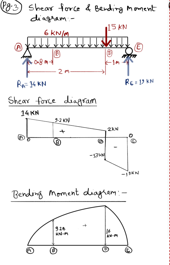
 15 kN 6 kN/m 100 mm AC E NA - B D 100 mm 0.8 m 2. (30pts.) For the truss system shown, a. (10 pts) Draw the shear and moment diagrams for the rectangular wooden beam shown. b. (6 pts )Determine the magnitude of the absolute maximum moment (Mmax) and its location c. (7 pts) Find the maximum bending stress in the member (max) d. (7 pts)Compute the Bending Stress at a point on the section B that is...
15 KN 6 km 100 m NA -- B D 100 m 2. (30pts.) For the...
 15 KN 6 km 100 m NA -- B D 100 m 2. (30pts.) For the truss system shown, a. (10 pts) Draw the shear and moment diagrams for the rectangular wooden beam shown. b. (6 pts)Determine the magnitude of the absolute maximum moment ( M.) and its location c. (7pts) Find the maximum bending stress in the member (O) d. (7 pts Compute the Banding Stress at a point on the section that is 25 mm below the top...
IS IN 6kN/m 100 mm E NA - M 08m 2. (Bpts) For the truss system...
 IS IN 6kN/m 100 mm E NA - M 08m 2. (Bpts) For the truss system show, a. (10 pts) Draw the shear and moment diagrams for the rectangular wooden beam shown. b. (6 pts Determine the magnitude of the absolute maximum moment (M...) and its location 1 pts) Find the maximum bending stress in the member (..) d. (7 pts Compute the Bending Stress at a point on the section that is 25 mm below the top of the...
20 KN 3 kN/m 3 2 KN- y, 2 kN-m 12.5 mm 200 mm? Z B...
 20 KN 3 kN/m 3 2 KN- y, 2 kN-m 12.5 mm 200 mm? Z B 150 mm 121.43 mm 1.5 m 1.5 m 2.2 m 12.5 mm Part [1] (a.) Construct shear and bending moment diagrams. Show all work. Label completely. (b.) Determine the maximum value of the transverse shear force (in magnitude) and where it occurs. 'Box' answers. (c.) Determine the maximum values of the bending moment (both positive and negative) and where each occurs. 'Box' answers. Part...
Q4. (20 pts) A kN/m BEN. X mm The beam has the cross-sectional area and loaded...
 Q4. (20 pts) A kN/m BEN. X mm The beam has the cross-sectional area and loaded as shown. Draw the bending and shear force diagrams. Find the maximum bending stress in the beam. التسعي HO Z mm Y mm 3 m Z mm A=40 X=75 B=25 Y=125 Z=10
If the beam is subjected to a positive bending moment of M = 100 kN-m, determine...
 If the beam is subjected to a positive bending moment of M = 100 kN-m, determine the maximum and minimum bending stress. Also determine the shear stress at point, A which is 50 mm above from the bottom. The cross-section of the beam is I-shaped and shown in the figure. 300 mm 30 mm 300 mm . 50 mm 30 mm
As shown in Figure 8, the structural member (beam) is 7m long, carries a 2 kN point load, a 1.2 kN/m uniformly distribu...
 As shown in Figure 8, the structural member (beam) is 7m long, carries a 2 kN point load, a 1.2 kN/m uniformly distributed load and is supported at points A and B. The beam is constructed from two pieces of steel plate (2 at 80mm x 8mm) that are welded together with 3mm welds. Section properties for the beam are also listed. Given the support reactions as RAv 5.8 kN and RBv 2.2 kN, as well as the shear force...
Problem 2: For the beam shown below: 16.0 kN/m 8.0 kN/m 16.8 mm 354 mm 9.4...
 Problem 2: For the beam shown below: 16.0 kN/m 8.0 kN/m 16.8 mm 354 mm 9.4 mm 50 kN 205 mm 4.0 m Beam Cross Section 4.0 m 4.0 m (a) Draw and label the axial, shear, and bending moment diagrams for the beam. (b) Determine the location and magnitude of maximum forces in the beam (axial, shear, and moment). (c) At the location of the maximum forces, draw the distribution of normal and shear stresses over the depth of...
Quiz # 5 60 kN 100 N 20 KN m 18 m 0.9 m For the...
 Quiz # 5 60 kN 100 N 20 KN m 18 m 0.9 m For the beam and loading shown a) Draw shear and moment diagram b) Determine maximum shear and maximum moment values c) Calculate the maximum normal stress due to bending, in the U-shaped section of the beam, which is placed with an inclination of 30° with the vertical as shown.
 15 kN 6 kN/m 100 mm AC E NA - B D 100 mm 0.8 m 2. (30pts.) For the truss system shown, a. (10 pts) Draw the shear and moment diagrams for the rectangular wooden beam shown. b. (6 pts )Determine the magnitude of the absolute maximum moment (Mmax) and its location c. (7 pts) Find the maximum bending stress in the member (max) d. (7 pts)Compute the Bending Stress at a point on the section B that is...
 15 KN 6 km 100 m NA -- B D 100 m 2. (30pts.) For the truss system shown, a. (10 pts) Draw the shear and moment diagrams for the rectangular wooden beam shown. b. (6 pts)Determine the magnitude of the absolute maximum moment ( M.) and its location c. (7pts) Find the maximum bending stress in the member (O) d. (7 pts Compute the Banding Stress at a point on the section that is 25 mm below the top...
 IS IN 6kN/m 100 mm E NA - M 08m 2. (Bpts) For the truss system show, a. (10 pts) Draw the shear and moment diagrams for the rectangular wooden beam shown. b. (6 pts Determine the magnitude of the absolute maximum moment (M...) and its location 1 pts) Find the maximum bending stress in the member (..) d. (7 pts Compute the Bending Stress at a point on the section that is 25 mm below the top of the...
 20 KN 3 kN/m 3 2 KN- y, 2 kN-m 12.5 mm 200 mm? Z B 150 mm 121.43 mm 1.5 m 1.5 m 2.2 m 12.5 mm Part [1] (a.) Construct shear and bending moment diagrams. Show all work. Label completely. (b.) Determine the maximum value of the transverse shear force (in magnitude) and where it occurs. 'Box' answers. (c.) Determine the maximum values of the bending moment (both positive and negative) and where each occurs. 'Box' answers. Part...
 Q4. (20 pts) A kN/m BEN. X mm The beam has the cross-sectional area and loaded as shown. Draw the bending and shear force diagrams. Find the maximum bending stress in the beam. التسعي HO Z mm Y mm 3 m Z mm A=40 X=75 B=25 Y=125 Z=10
 If the beam is subjected to a positive bending moment of M = 100 kN-m, determine the maximum and minimum bending stress. Also determine the shear stress at point, A which is 50 mm above from the bottom. The cross-section of the beam is I-shaped and shown in the figure. 300 mm 30 mm 300 mm . 50 mm 30 mm
 If the beam is subjected to a positive bending moment of M = 100 kN-m, determine the maximum and minimum bending stress. Also determine the shear stress at point, A which is 50 mm above from the bottom. The cross-section of the beam is I-shaped and shown in the figure. 300 mm 30 mm 300 mm . 50 mm 30 mm
 As shown in Figure 8, the structural member (beam) is 7m long, carries a 2 kN point load, a 1.2 kN/m uniformly distributed load and is supported at points A and B. The beam is constructed from two pieces of steel plate (2 at 80mm x 8mm) that are welded together with 3mm welds. Section properties for the beam are also listed. Given the support reactions as RAv 5.8 kN and RBv 2.2 kN, as well as the shear force...
 Problem 2: For the beam shown below: 16.0 kN/m 8.0 kN/m 16.8 mm 354 mm 9.4 mm 50 kN 205 mm 4.0 m Beam Cross Section 4.0 m 4.0 m (a) Draw and label the axial, shear, and bending moment diagrams for the beam. (b) Determine the location and magnitude of maximum forces in the beam (axial, shear, and moment). (c) At the location of the maximum forces, draw the distribution of normal and shear stresses over the depth of...
 Quiz # 5 60 kN 100 N 20 KN m 18 m 0.9 m For the beam and loading shown a) Draw shear and moment diagram b) Determine maximum shear and maximum moment values c) Calculate the maximum normal stress due to bending, in the U-shaped section of the beam, which is placed with an inclination of 30° with the vertical as shown.
Most questions answered within 3 hours.
-
Hyundai Motors is considering threesites—A, B,C —at which to
locate a factory to build its new-model...
asked 1 minute from now -
Learning Outcomes:
Upon the successful completion of this module, you should
understand the following concepts:
Strategic...
asked 2 seconds from now -
A 0.2m diameter ball with an initial velocity of 8m/s rolls up a
hill without slipping....
asked 7 minutes ago -
Identify four of the five major types of organizations within
the federal bureaucracy, and give examples...
asked 8 minutes ago -
The following data have been obtained
for the effect of solvent composition on the solubility of...
asked 8 minutes ago -
Our ability to see distinct edges as well as our errors in
contrast perceptions (e.g., seeing...
asked 27 minutes ago -
Two buckets of mass 17.1 kg and 11.3 kg are attached to the ends
of a...
asked 20 minutes ago -
A laser used in LASIK eye surgery produces 50 pulses per second.
The wavelength is 192...
asked 18 minutes ago -
Smith Inc. recently reported operating income of $2.75 million,
depreciation of $1.20 million, and had a...
asked 18 minutes ago -
A
nurse is trying to understand the structure and chain of command of
a healthcare organization....
asked 21 minutes ago -
A company is interested in estimating the costs of lunch
in their cafeteria. After surveying employees,...
asked 25 minutes ago -
A woman expends 94 kJ of energy in walking a kilometer. The
energy is supplied by...
asked 36 minutes ago