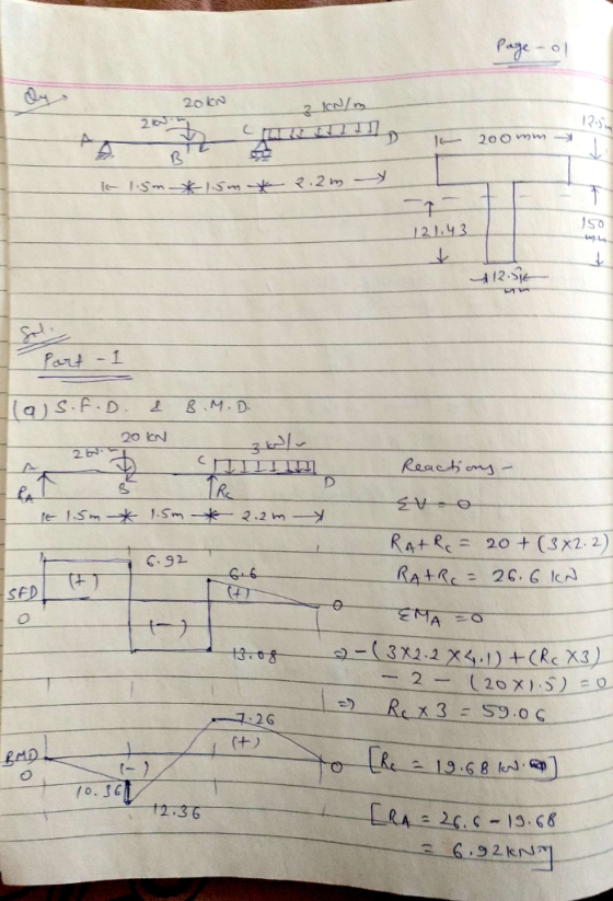
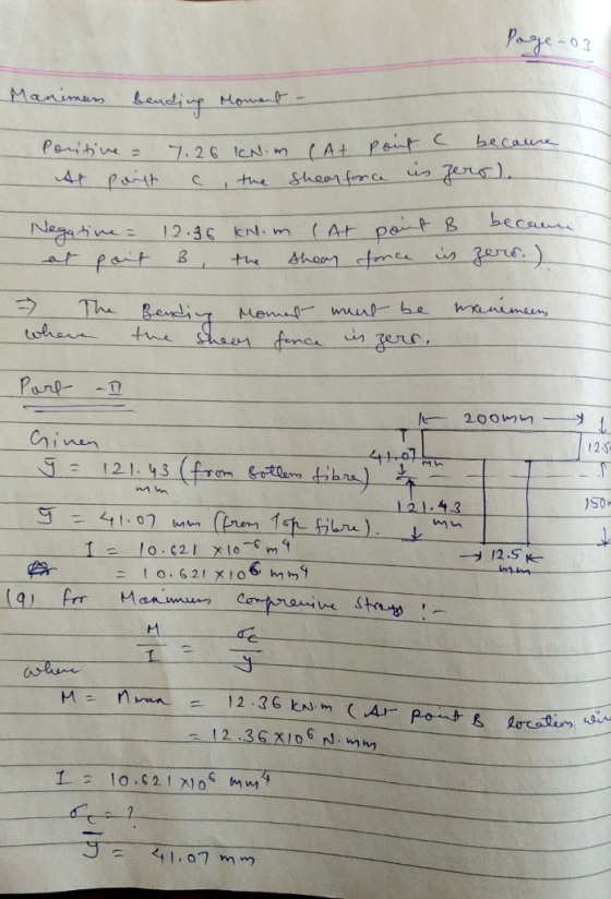
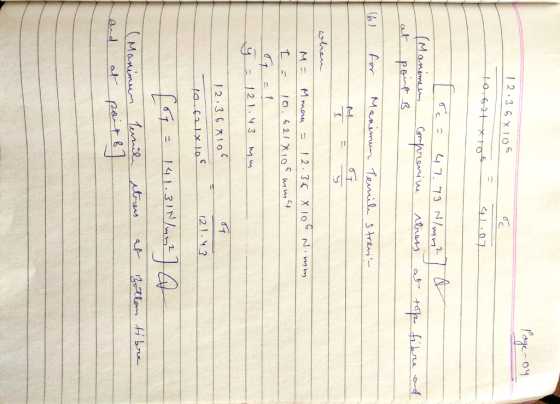
![20 KN 3 kN/m 3 2 KN- y, 2 kN-m 12.5 mm 200 mm? Z B 150 mm 121.43 mm 1.5 m 1.5 m 2.2 m 12.5 mm Part [1] (a.) Construct shear and bending moment diagrams. Show all work. Label completely. (b.) Determine the maximum value of the transverse shear force (in magnitude) and where it occurs. Box answers. (c.) Determine the maximum values of the bending moment (both positive and negative) and where each occurs. Box answers. Part 21 The cross-sectional geometry is shown for this same beam and loading above. The location of the centroid of the cross-section is shown (121.43 mm from the bottom). The second moment of area (moment of inertia) about the z axis is: Iz = 10.621 x 106 mm4 = 10.621 x 10⁻⁶ m (a.) Determine the maximum compressive normal stress due to bending and indicate where it occurs (location along the length, plus top or bottom). Show all work. Box answers. (b.) Determine the maximum tensile normal stress due to bending and indicate where it occurs (location along the length, plus top or bottom). Show all work. Box answers.](http://img.homeworklib.com/questions/e1ed41b0-d25d-11ea-9f86-73835710dc44.png?x-oss-process=image/resize,w_560)
Homework Answers

6 kN/m 15 kN 100 mm E NA - B D 100 mm 0.8 m For...
 6 kN/m 15 kN 100 mm E NA - B D 100 mm 0.8 m For the truss system shown, a. (10 pts) Draw the shear and moment diagrams for the rectangular wooden beam shown. b. (6 pts)Determine the magnitude of the absolute maximum moment (Mmax) and its location c. (Z pts) Find the maximum bending stress in the member (max) d. (Z pts)Compute the Bending Stress at a point on the section B that is 25 mm below the...
For the beam and loading shown below, 3 kN 3 KN 1.8 kN/m SO mm B...
 For the beam and loading shown below, 3 kN 3 KN 1.8 kN/m SO mm B 300 mm D 1 - -1.5 m 1,5 m - 1.5 m Q2-PART@) Determine the reaction force at A = ? (in kN) Q2-PART(b) Determine the moment inertia along the horizontal neutral axis for the cross section of the beam = ? (in 106 mm) Q2-PARI(C) Determine the maximum normal stress due to bending on a transverse section at C = ? (in MPa)
15 kN 6 kN/m 100 mm AC E NA - B D 100 mm 0.8 m...
 15 kN 6 kN/m 100 mm AC E NA - B D 100 mm 0.8 m 2. (30pts.) For the truss system shown, a. (10 pts) Draw the shear and moment diagrams for the rectangular wooden beam shown. b. (6 pts )Determine the magnitude of the absolute maximum moment (Mmax) and its location c. (7 pts) Find the maximum bending stress in the member (max) d. (7 pts)Compute the Bending Stress at a point on the section B that is...
2. (32 pts) Two identical 20 mm thick plates are bolted to the top and bottom...
 2. (32 pts) Two identical 20 mm thick plates are bolted to the top and bottom Mange to form the build-up heam. If the beam is subjected to a shear force of V = 300 KN and a bending moment of M = 500 KN-m. d) Calculate the shear stress between flange plates. If each bolt has a shear strength of 30 KN, determine a) Calculate moment of inertia of the cross section in the z axis. b) Calculate the...
Problem 2: For the beam shown below: 16.0 kN/m 8.0 kN/m 16.8 mm 354 mm 9.4...
 Problem 2: For the beam shown below: 16.0 kN/m 8.0 kN/m 16.8 mm 354 mm 9.4 mm 50 kN 205 mm 4.0 m Beam Cross Section 4.0 m 4.0 m (a) Draw and label the axial, shear, and bending moment diagrams for the beam. (b) Determine the location and magnitude of maximum forces in the beam (axial, shear, and moment). (c) At the location of the maximum forces, draw the distribution of normal and shear stresses over the depth of...
4. A T-shaped cross-sectional beam is loaded as shown in the figure. Determine the following a....
 4. A T-shaped cross-sectional beam is loaded as shown in the figure. Determine the following a. Sketch the internal shear force and bending moment diagrams for the beam. b. Calculate the maximum magnitude of the bending stress. Indicate where this occurs on the cross-section and along the length of the beam. c. Calculate the transverse shearing stress at the centroid of the cross-section using the maximum magnitude of the transverse shear force. - 200 mm 8 KN 1.5 kN/m 20...
10 mm 10 mm 300 N/m 50 mm 10 mm Problem 2. Consider the beam above with the cross-section shown. ...
 please solve 1-5 and show all steps and equations used
10 mm 10 mm 300 N/m 50 mm 10 mm Problem 2. Consider the beam above with the cross-section shown. The number (300N/m) indicates the value of the load distribution at its peak. (5 pts.) Find the reactions (15 pts.) Draw the shear and moment diagrams using the graphical method. Ensure you state values of the diagrams, and type of function for lincar or higher-order segments. You can indicate all...
please solve 1-5 and show all steps and equations used
10 mm 10 mm 300 N/m 50 mm 10 mm Problem 2. Consider the beam above with the cross-section shown. The number (300N/m) indicates the value of the load distribution at its peak. (5 pts.) Find the reactions (15 pts.) Draw the shear and moment diagrams using the graphical method. Ensure you state values of the diagrams, and type of function for lincar or higher-order segments. You can indicate all...
IS IN 6kN/m 100 mm E NA - M 08m 2. (Bpts) For the truss system...
 IS IN 6kN/m 100 mm E NA - M 08m 2. (Bpts) For the truss system show, a. (10 pts) Draw the shear and moment diagrams for the rectangular wooden beam shown. b. (6 pts Determine the magnitude of the absolute maximum moment (M...) and its location 1 pts) Find the maximum bending stress in the member (..) d. (7 pts Compute the Bending Stress at a point on the section that is 25 mm below the top of the...
As shown in Figure 8, the structural member (beam) is 7m long, carries a 2 kN point load, a 1.2 kN/m uniformly distribu...
 As shown in Figure 8, the structural member (beam) is 7m long, carries a 2 kN point load, a 1.2 kN/m uniformly distributed load and is supported at points A and B. The beam is constructed from two pieces of steel plate (2 at 80mm x 8mm) that are welded together with 3mm welds. Section properties for the beam are also listed. Given the support reactions as RAv 5.8 kN and RBv 2.2 kN, as well as the shear force...
If the beam is subjected to a positive bending moment of M = 100 kN-m, determine...
 If the beam is subjected to a positive bending moment of M = 100 kN-m, determine the maximum and minimum bending stress. Also determine the shear stress at point, A which is 50 mm above from the bottom. The cross-section of the beam is I-shaped and shown in the figure. 300 mm 30 mm 300 mm . 50 mm 30 mm
 6 kN/m 15 kN 100 mm E NA - B D 100 mm 0.8 m For the truss system shown, a. (10 pts) Draw the shear and moment diagrams for the rectangular wooden beam shown. b. (6 pts)Determine the magnitude of the absolute maximum moment (Mmax) and its location c. (Z pts) Find the maximum bending stress in the member (max) d. (Z pts)Compute the Bending Stress at a point on the section B that is 25 mm below the...
 For the beam and loading shown below, 3 kN 3 KN 1.8 kN/m SO mm B 300 mm D 1 - -1.5 m 1,5 m - 1.5 m Q2-PART@) Determine the reaction force at A = ? (in kN) Q2-PART(b) Determine the moment inertia along the horizontal neutral axis for the cross section of the beam = ? (in 106 mm) Q2-PARI(C) Determine the maximum normal stress due to bending on a transverse section at C = ? (in MPa)
 15 kN 6 kN/m 100 mm AC E NA - B D 100 mm 0.8 m 2. (30pts.) For the truss system shown, a. (10 pts) Draw the shear and moment diagrams for the rectangular wooden beam shown. b. (6 pts )Determine the magnitude of the absolute maximum moment (Mmax) and its location c. (7 pts) Find the maximum bending stress in the member (max) d. (7 pts)Compute the Bending Stress at a point on the section B that is...
 2. (32 pts) Two identical 20 mm thick plates are bolted to the top and bottom Mange to form the build-up heam. If the beam is subjected to a shear force of V = 300 KN and a bending moment of M = 500 KN-m. d) Calculate the shear stress between flange plates. If each bolt has a shear strength of 30 KN, determine a) Calculate moment of inertia of the cross section in the z axis. b) Calculate the...
 Problem 2: For the beam shown below: 16.0 kN/m 8.0 kN/m 16.8 mm 354 mm 9.4 mm 50 kN 205 mm 4.0 m Beam Cross Section 4.0 m 4.0 m (a) Draw and label the axial, shear, and bending moment diagrams for the beam. (b) Determine the location and magnitude of maximum forces in the beam (axial, shear, and moment). (c) At the location of the maximum forces, draw the distribution of normal and shear stresses over the depth of...
 4. A T-shaped cross-sectional beam is loaded as shown in the figure. Determine the following a. Sketch the internal shear force and bending moment diagrams for the beam. b. Calculate the maximum magnitude of the bending stress. Indicate where this occurs on the cross-section and along the length of the beam. c. Calculate the transverse shearing stress at the centroid of the cross-section using the maximum magnitude of the transverse shear force. - 200 mm 8 KN 1.5 kN/m 20...
 please solve 1-5 and show all steps and equations used
10 mm 10 mm 300 N/m 50 mm 10 mm Problem 2. Consider the beam above with the cross-section shown. The number (300N/m) indicates the value of the load distribution at its peak. (5 pts.) Find the reactions (15 pts.) Draw the shear and moment diagrams using the graphical method. Ensure you state values of the diagrams, and type of function for lincar or higher-order segments. You can indicate all...
please solve 1-5 and show all steps and equations used
10 mm 10 mm 300 N/m 50 mm 10 mm Problem 2. Consider the beam above with the cross-section shown. The number (300N/m) indicates the value of the load distribution at its peak. (5 pts.) Find the reactions (15 pts.) Draw the shear and moment diagrams using the graphical method. Ensure you state values of the diagrams, and type of function for lincar or higher-order segments. You can indicate all...
 IS IN 6kN/m 100 mm E NA - M 08m 2. (Bpts) For the truss system show, a. (10 pts) Draw the shear and moment diagrams for the rectangular wooden beam shown. b. (6 pts Determine the magnitude of the absolute maximum moment (M...) and its location 1 pts) Find the maximum bending stress in the member (..) d. (7 pts Compute the Bending Stress at a point on the section that is 25 mm below the top of the...
 As shown in Figure 8, the structural member (beam) is 7m long, carries a 2 kN point load, a 1.2 kN/m uniformly distributed load and is supported at points A and B. The beam is constructed from two pieces of steel plate (2 at 80mm x 8mm) that are welded together with 3mm welds. Section properties for the beam are also listed. Given the support reactions as RAv 5.8 kN and RBv 2.2 kN, as well as the shear force...
 If the beam is subjected to a positive bending moment of M = 100 kN-m, determine the maximum and minimum bending stress. Also determine the shear stress at point, A which is 50 mm above from the bottom. The cross-section of the beam is I-shaped and shown in the figure. 300 mm 30 mm 300 mm . 50 mm 30 mm
Most questions answered within 3 hours.
-
The equilibrium constant for the following reaction Ag+(aq) +
2NH3(aq) Ag(NH3)2+(aq) is K = 1.7 ×...
asked 1 minute from now -
Suppose X∼Exp(λ) for some λ >0. Compute E(X) and Var(X).
asked 13 minutes ago -
Xanth Co. has 8.9% annual coupon bonds with face value of $1,000
and 7 years remaining...
asked 10 minutes ago -
The Bellevue University bookstore purchases sweatshirts with the
school name and logo from a vendor. The...
asked 14 minutes ago -
If you invest the $10,000 you receive at graduation in a mutual
fund which averages a...
asked 16 minutes ago -
Consider 15 mL of an aqueous solution containing 2.0 g of an
organic solute.If the distribution...
asked 16 minutes ago -
Define the following Marketing Psychology Principles of Human
Behavior: Priming, Reciprocity, Social Proof, Decoy Effect,
Scarcity,...
asked 32 minutes ago -
What does the graph of Range vs angle look like? Also what is
the slope of...
asked 35 minutes ago -
a
sample size of _ is needed So there a 99% confidence interval will
have a...
asked 40 minutes ago -
Strategy is an important part of project management and business
decisions. Define strategy and describe in...
asked 43 minutes ago -
Task 5.2 Numerical Analysis Using Nested Loops (13 pts)
Consider the following program:
void setup()
{...
asked 57 minutes ago -
If a lossless transformer has 1000 turns for a primary winding
and 100 turns for the...
asked 1 hour ago